11
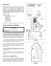
positions of the arm). Use a 10mm hex wrench to
remove or install the work stop.
BELT ARM POSITIONING
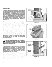
Your sander is equipped with a shot pin arrangement to
lock the belt arm in 0-degree, 45-degree, and 90 degree
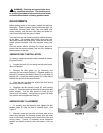
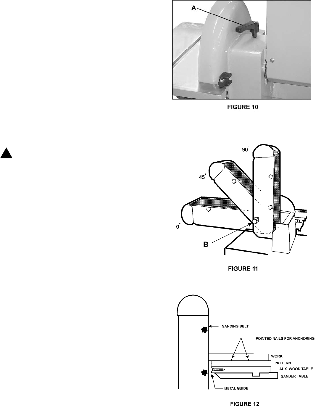
positions. To position the belt, loosen the locking handle
(A) shown in Figure 10. Pull out on the shot pin (B),
shown in Figure 11, and swing the belt arm into the
desired position. Then release the shot pin. Check that
the pin has gone into position by attempting to move belt
arm back and forth. Re-tighten locking handle (A-Figure
10). When positioning the arm at any non-standard
angle, make sure the locking handle is tightened
securely.
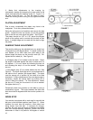
NOTE: If the locking handle conflicts with the motion of
the belt arm, pull up on the handle and turn it out of the
way, as shown in Figure 10.
CHANGING MOTOR VOLTAGE
WARNING: ELECTRICAL WIRING SHOULD
BE DONE BY A QUALIFIED ELECTRICIAN. THE
MACHINE MUST BE PROPERLY GROUNDED TO
HELP AVOID ELECTRICAL SHOCK AND
ASSOCIATED HAZARDS INCLUDING POSSIBLE
DEATH.
To change the motor voltage, remove the terminal box
cover and rewire per the circuit shown on the cover. On
magnetic starter models, starter wiring and transformer
wiring (when used) will also have to be changed as
shown on the decals attached.
OPERATING THE SANDER
The belt and disc sander can be equipped with a variety
of abrasives and grit sizes to handle a wide variety of
materials, from soft woods to hardened steel. It can be
used to rapidly remove material and produce a mirror
finish. Using various types of fixtures, they can be used
to sand template forms, angles, freehand contours, and
flats on edges, surfaces and ends.
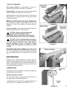
TEMPLATE FORMS
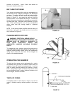
A template similar to that shown in Figure 12, can be
made to faciliate sanding multiple pieces to the same
size.
!


