


8
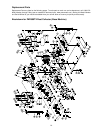
Base Machine Assembly
The dust collector must not be
connected to the power source
during assembly.
All instructions on this page refer to Figure 3.
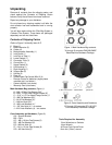
Base and Base Extensions
1. Attach the base extensions (L) to the base (K)
by inserting M8x20 hex head screws (A)
through the mounting holes of the extension (L)
and base (K).
2. Place M8 flat washers (D) and M8 lock washers
(G) on the ends of the screws (A) and fasten
with M8 hex nuts (F), using 13mm wrenches.
Casters
1. The 3/8” hex nut (H) and M10 lock washer (J)
are pre-assembled to each caster (M). For
shipping purposes, the lock washer has been
placed beneath the hex nut. Remove hex nut
and lock washer from the caster shaft, re-install
the hex nut, then install the lock washer above
the hex nut, as shown.
2. Install the four casters (M) to the underside of
the base (K) as follows:
3. Thread the caster shaft into the threaded hole
on the underside of the base (K), turn until
snug. Tighten the hex nut (H) against the base
with a 14mm wrench.
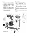
Motor and Impeller Assembly
1. Place the base with casters down on the ground.
2. Attach the motor and impeller assembly (N) to the
base (K) using six M8x20 hex cap screws (A),
and six M10 flat washers (E). Hand tighten only
until all screws and washers are in place, then
tighten all six screws with a 13mm wrench.
3. Attach the inlet guard (O) to impeller housing (N)
using eight M6x12 pan head flange screws (B).
4. Press the inlet port (P) onto the inlet guard (O)
until it snaps into place. Secure in place with
3/16” x 1/2” pan head flange screw (C).
To reduce the risk of injury from
moving parts, always keep inlet port (P) covered
with the caps provided, if they are not connected
to a hose.
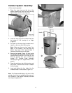
Connector Tube and Switch Box
1. Place the lower gasket (Q) on the impeller
housing (N). Line up the rubber pegs on the
gasket (face down) with the holes in the housing.
2. Place the connector tube (R) on the impeller
housing (N), making sure that the holes of the
mating flanges are aligned.
Note: Refer to Figure 3 to make sure that the
connector tube is facing the proper direction.
3. Insert an M8x20 hex cap screw (A), through the
M8 washer (D) and flanges of the connector tube
(R) and impeller housing (N).
4. Place another washer (D) and a hex nut (F) on
the protruding end of the screw (A) and hand-
tighten only.
5. Mount the control box (S) to the two holes at the
front of the connector tube flange (R).
6. Repeat steps 3 and 4 for the remaining screw
locations, hand tightening only.
7. Tighten all hex nuts with a 13mm wrench.
Collector Housings
Mount the right collector housing (V) as follows:
1. Place an upper gasket (T) between the collector
housing (V) and connector tube (R). Line up the
pegs on the gasket (T) with the holes in the
housing (V).
2. Place the collector housing (V) on the connector
tube (R). Make sure to properly orient the
collector housing – the internal baffle must slope
downwards toward the center.
3. Insert a screw (A) through the washer (D),
connector tube flange (R), and collector-housing
flange (V).
4. Place another washer (D) and a hex nut (F) on
the protruding end of the screw (A) and hand-
tighten.
5. Repeat steps 1 through 4 for the seven remaining
screw locations.
6. Tighten all screws and hex nuts with a 13mm
wrench.
7. Repeat steps 1 through 6 for the left collector
housing (U).
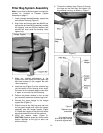
Support Bars
1. Align the bottom slots of a support bar (W) with
the holes in the base (K). Insert two screws (A)
with two flat washers (D) and hand tighten only.
Note: If you are using the Canister Filter
System, proceed with steps 2 through 5 below.
If you are using the Filter Bag System, leave
the support bar (W) as is, for further assembly
later, and proceed to “Handles”.
2. Align the top holes of the support bar (W) with
the holes at the rear of the collector housing (V)
and insert two screws (A) and two flat washers
(D).
3. Place a washer (D) and a hex nut (F) on the
protruding end of each screw (A) inside the
collector housing, and hand-tighten only.
4. Adjust the lower part of the support bar (W) as
needed using its slots, until it is straight. Then
tighten all four screws on the support bar (W).
5. Repeat for the other support bar.