


14
Grounding Instructions
Electrical connections must be
made by a qualified electrician in compliance
with all relevant codes. This machine must be
properly grounded to help prevent electrical
shock and possible fatal injury.
A power plug is not provided with the Model 2000.
You may either connect the proper UL/CSA listed
plug or “hardwire” the machine directly to your
electrical panel provided there is a disconnect near
the machine for the operator. Consult electrical
drawings on pages 38-41 for further clarification of
wiring setup.
This machine must be grounded. Grounding
provides a path of least resistance to help divert
current away from the operator in case of electrical
malfunction.
Make sure the voltage of your power supply
matches the specifications on the motor plate of the
machine.
Extension Cords
If an extension cord is necessary, make sure the
cord rating is suitable for the amperage listed on
the machine's motor plate. An undersized cord will
cause a drop in line voltage resulting in loss of
power and overheating.
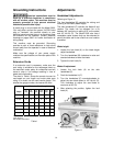
The chart in Table 1 shows the correct size cord to
use based on cord length and motor plate amp
rating. If in doubt, use the next heavier gauge. The
smaller the gauge number, the heavier the cord.
Amps
Extension Cord Length *
25
feet
50
feet
75
feet
100
feet
150
feet
200
feet
< 5 16 16 16 14 12 12
5 to 8 16 16 14 12 10 NR
8 to 12 14 14 12 10 NR NR
12 to 15 12 12 10 10 NR NR
15 to 20 10 10 10 NR NR NR
21 to 30 10 NR NR NR NR NR
*based on limiting the line voltage drop to 5V at 150% of the
rated amperes.
NR: Not Recommended.
Table 1
A
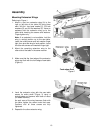
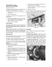
djustments
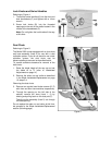
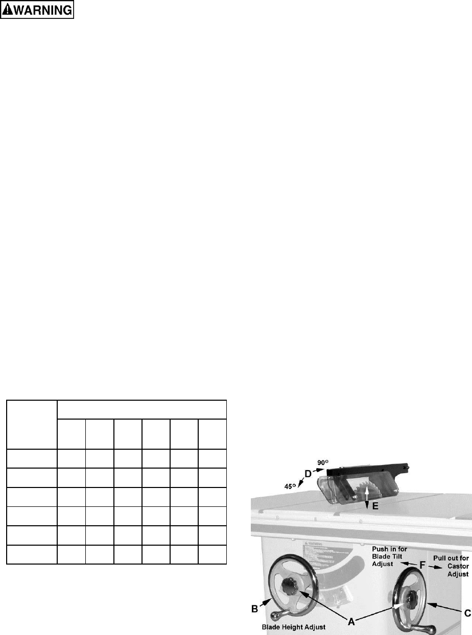
Handwheel Adjustments
Referring to Figure 11:
The front handwheel (B) controls the raising and
lowering of the blade (blade height).
The side handwheel (C) controls the blade tilt and
castors. The blade can be adjusted for a tilt
between 90º (vertical or a setting of 0º on the scale)
and 45º left tilt (D). The Model 2000 also has a
retractable castor system that can be extended to
permit the table saw to be rolled from one location
to another.
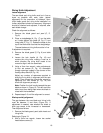
Blade height
1. Loosen the lock knob (A) on the blade height
adjust handwheel.
2. Turn the handwheel (B) clockwise to raise and
counterclockwise to lower the blade.
3. Tighten the lock knob (A).
Blade tilt adjustment
1. Loosen the lock knob (A) on the side
handwheel (C).
2. Push the handwheel in (F).
3. Turn the handwheel (C) counterclockwise to
adjust the saw blade down to 45º left tilt (D).
Turn clockwise to adjust the saw blade to
maximum of 90º (D).
4. After selecting the position, tighten the lock
knob (A).
Figure 11