10
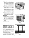
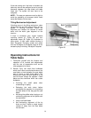
2. With a 3/8" wrench, reach through the motor
opening in the stand and tighten the square
head setscrew (A, Figure 8) into the groove
of the shaft. (NOTE: The groove will be in
the proper position if the end of the shaft is
made flush with the opposite side of the
trunnion hole.) Then tighten the hex nut (B,
Figure 8) up against the trunnion.
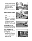
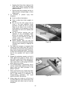
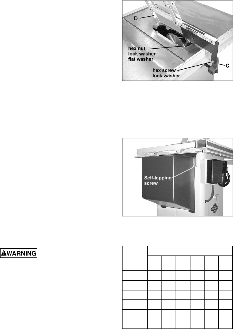
3. The upright member of the rear splitter
support (C, Figure 9) must be oriented
toward the right of the shaft, as observed
from the rear of the saw.
4. Mount the splitter assembly to the two
adjusting screws. See Figure 9. Place the
two flanges of the splitter assembly onto the
s
crews as shown. Snug the screws. (NOTE:
Make sure the front shield (D, Figure 9)
faces in toward the blade)
5. The splitter and guard assembly must be
aligned with the blade before operating the
saw. Adjust the splitter according to the
directions on page 13, "Splitter Alignment."
Motor Cover
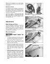
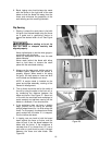
1. Locate the two 1/4-20 self tapping sheet
metal screws and install them in the
punched holes on the saw cabinet. Do not
screw down all the way, but leave the heads
about 1/4" from the surface. See Figure 10.
2. Lift the motor cover over these screws with
the cover's bottom lip inside the saw's
cabinet.
3. Tighten the two screws.
Grounding Instructions
Electrical connections must
be made by a qualified electrician in
compliance with all relevant codes. This
machine must be properly grounded to help
prevent electrical shock and possible fatal
injury.
A power plug is not provided with the Model 66.
You may either connect the proper UL/CSA
listed plug or “hardwire” the machine directly to
your electrical panel provided there is a
disconnect near the machine for the operator.
Consult electrical drawings on pages 33-36 for
further clarification of wiring setup.
This machine must be grounded. Grounding
provides a path of least resistance to help divert
current away from the operator in case of
electrical malfunction.
Figure 9
Figure 10
Recommended Gauges (AWG) of Extension Cords
Extension Cord Length *
Amps
25
feet
50
feet
75
feet
100
feet
150
feet
200
feet
< 5 16 16 16 14 12 12
5 to 8 16 16 14 12 10 NR
8 to 12 14 14 12 10 NR NR
12 to 15 12 12 10 10 NR NR
15 to 20 10 10 10 NR NR NR
21 to 30 10 NR NR NR NR NR
*based on limiting the line voltage drop to 5V at 150% of the
rated amperes.
NR: Not Recommended.
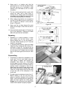
Figure 11


