


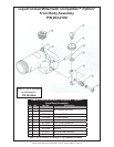
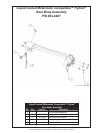
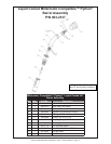
Liquid Cooled Millermatic Compatible™ Python
®
Owner's Manual - Page 8
Disconnect Power
Before Troubleshooting.
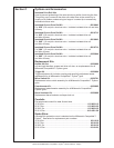
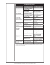
Section E Troubleshooting Guide
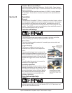
To aid in troubleshooting problems with your welding equipment, it is best
to understand the basic theory of operation for this Push-Pull System. The
slave motor in the feeder runs at a fast, constant speed, but has very low
torque. It is always trying to feed more wire than the gun motor wants,
and when the motor gets all it wants, it slows the slave motor, preventing
a bird’s nest. Because of the low torque produced by the slave motor, a
brake system is used to prevent wire overrun rather than tension. The drag
adjustment in the feeder is used simply to keep the wire slightly taut, so it will
not pull off the spool while feeding wire.
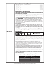
The high torque 24VDC gun motor is controlled by an electric speed
control located in the feeder, and a pot located in the gun. The gun motor,
potentiometer, and micro switch are connected to the cabinet/control box via
a control cable and connector. If this cable becomes damaged, a variety of
symptoms can occur, depending on which wire(s) break. To test, check each
wire for continuity and shorts.
Remember, the micro switch in the gun activates both the slave motor and
gun motor circuits in the cabinet. Therefore, if the slave motor and brake
solenoid operate, but the gun does not, look more toward the gun motor’s
24VDC circuits, speed control, control cable, or the gun motor. If nothing
operates, look more toward the slave motor’s input, micro switch leads, or
micro switch.
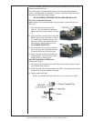
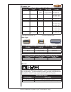
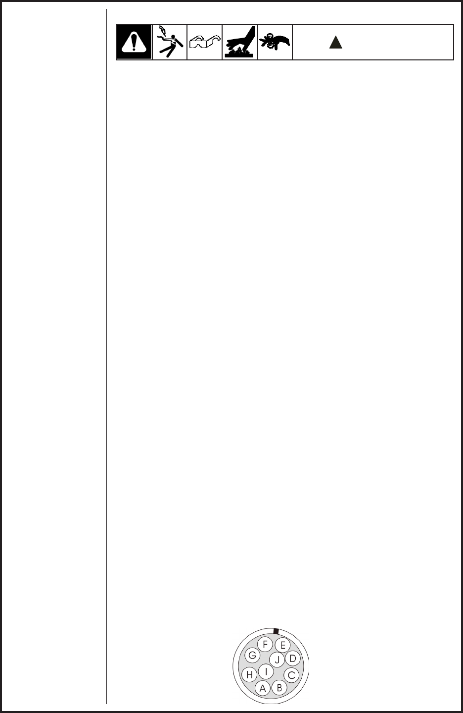
Testing The Gun
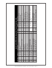
Reference the "X" clocked diagram
on the liquid cooled Millermatic Compatible™ Python
®
electrical diagram
for information about pin-outs and locations.
Motor Check
Remove the connector from the cabinet.
Using the connector, check the resistance across pins “C” and “B” (motor
leads). The resistance across the motor should be between 5 - 10 ohms as
the potentiometer is turned.
If an open circuit or short exist, check the motor leads and motor
independently.
Testing the Gun Potentiometer
Using the connector, check the resistance across pin “F” (wiper) and pin
“E”. The resistance should vary from 0 - 5K ohms as the potentiometer is
turned.
Check the resistance across pin “F” (wiper) and pin “H”. The resistance
should vary from 5K - 0 ohms as the potentiometer is turned.
Testing the Micro Switch
Using the connector, check for continuity across pins “D” and “G” when the
trigger is pressed.