3
Installation Tasks
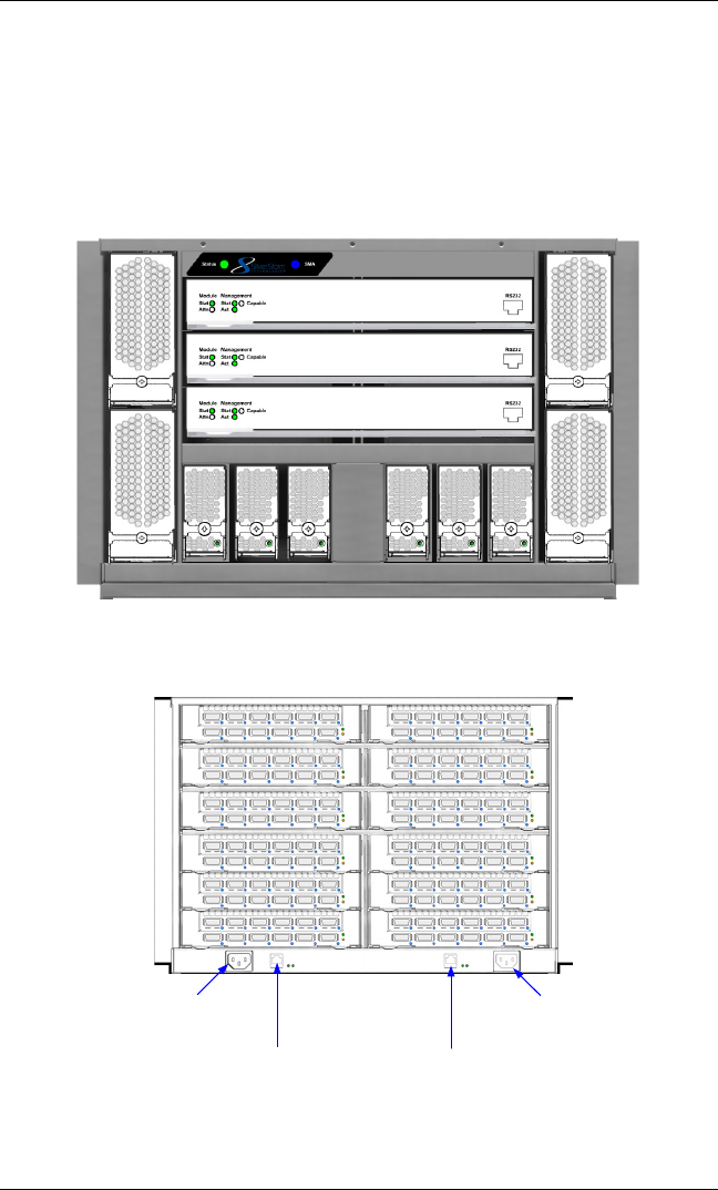
NOTE: Before performing the installation tasks, take a few minutes to review the figures below. It is important to understand
the slot numbering for the leaf modules and spine modules (and the corresponding spine RJ-45 ports). It is also important to
understand the slot numbering for the fans and power supplies (and the corresponding AC power inlets for the power supplies).
Figure 1. SilverStorm 9120 Chassis Front View
Figure 2. SilverStorm 9120 Chassis Back View
Spine 1 (Managed)
Fan
4
Fan
2
Fan
3
Fan
1
PS
6
PS
5
PS
4
PS
3
PS
2
PS
1
Spine 2 (Managed)
Spine 3 (Unmanaged)
Leaf 1
RJ-45 for Spine 1 RJ-45 for Spine 2
AC power inlet for power
supplies 4 to 6
Leaf 2
Leaf 4
Leaf 6
Leaf 8
Leaf 10
Leaf 12
Leaf 3
Leaf 5
Leaf 7
Leaf 9
Leaf 11
AC power inlet for power
supplies 1 to 3


