


4
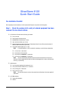
To perform the actual switch installation, the site implementation engineer must perform the following tasks, which are detailed
in this section.
Step 1. Check the installation site to verify the installation of cabinet
power feeds, rails, and grounding.
Step 2. Inspect the packaging and equipment for any shipping damage.
Any shipping damage should be reported to the shipping company. Only
unpack the the equipment if there is no shipping damage.
Step 3. Record the equipment serial numbers.
Step 4. Physically install the switch in the rack.
Step 5. Install InfiniBand (IB) or IB/Fiber Optic cables between the
SilverStorm 9120 and network devices.
Step 6. Install intra-cabinet power and grounding cables for the switch.
Step 7. Power up the switch.
Step 8. Change the default system IP address (192.168.100.9) and
gateway IP address (255.255.255.0) for the master spine.
Step 9. Add the equipment to the network.
Changing the IP Address and Default Gateway
Using the RS232 Serial Port
Step 1. Connect null-modem/crossover serial cables to the RS-232 port
of the switch spine module. If using a terminal emulation device, the settings
should be:
❑ 8 data bits
❑ no parity bits
❑ 1 stop bit
❑ 56K baud
❑ Use VT100 emulation.