


19Quadra-fire • QV32B-A, QV36B-A • 2014-900 Rev. F • 9/06
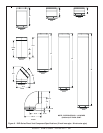
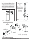
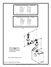
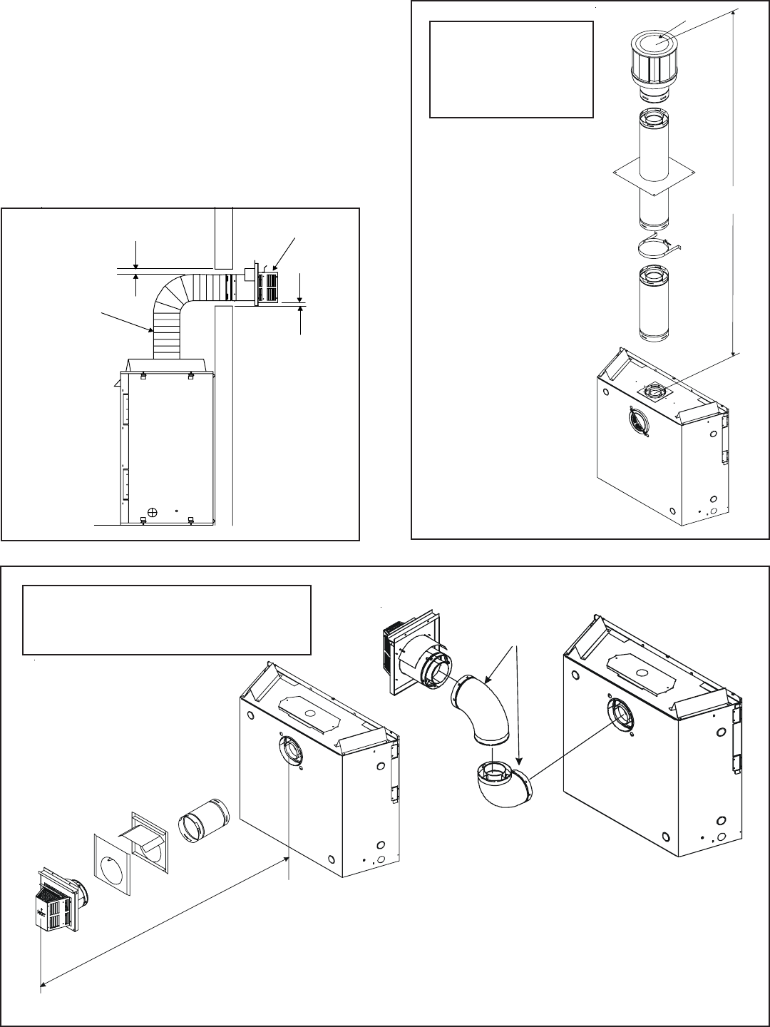
STRAIGHT UP
VERTICAL VENTING
V (FT.)
45' MAX.
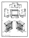
Figure 10.
Straight up Vertical Venting
Use SL D-Series
components only.
NOTE: For vertical venting
over 20 feet a restrictor
plate is recommended for
improved flame appearance.
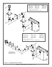
STRAIGHT OUT HORIZONTAL VENTING
H
Max. Run
36" (914 mm)
Use DVP-Series
components only.
Figure 11. Straight Out Horizontal Venting
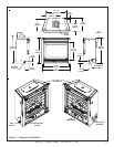
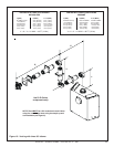
H
90-DEGREE
ELBOWS
Use two 90
0
elbows for corner installations.
The use of two 90
0
elbows in a corner installa-
tion will affect space requirements (see Fig. 4)
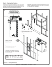
Figure 9.
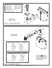
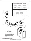
Flex Vent
The flex vent must be supported with the spacing between
support intervals not exceeding 4 feet, with no more than ½
inch sag between supports.
A support is required at each change in venting direction,
and in any location where it is necessary to maintain the
necessary clearance to combustibles. A simple “up and out”
installation (Figure 9) requires only enough support to main-
tain the necessary clearance to combustibles. However, the
vent attachment point and the firestop location are consid-
ered to be supports.
3” CLEARANCE
TERMINATION
CAP
FLEX-VENT
1”
CLEARANCE
V
CAP