


LABC1 • 14
Take a moment now to check your previous solder joints for “opens” where
the solder did not completely flow around the connection, or solder bridges
between closely spaced pads. It seems the best time to identify these
problems is now when you’re focused on this section of the board, saving you
time trying to retrace your steps later.
14. Install R2, the PC mount 1K ohm potentiometer (marked 102). It only
fits on the board one way; just be sure it is seated flat before soldering.
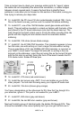
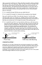
15. Install D17, one of the 1N4148 diodes (small glass diode with black
band). This part will be mounted in a stand-up fashion with the body of the
part placed in the PC board silkscreen circle and the black band up. The
lead closest to the band is bent over to fit into the other mounting hole. Be
gentle with this fragile part and double check the orientation before
soldering.
16. Install R8, 10K ohms (brown-black-orange).
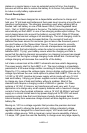
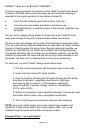
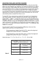
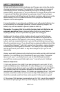
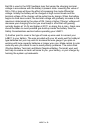
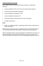
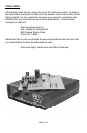
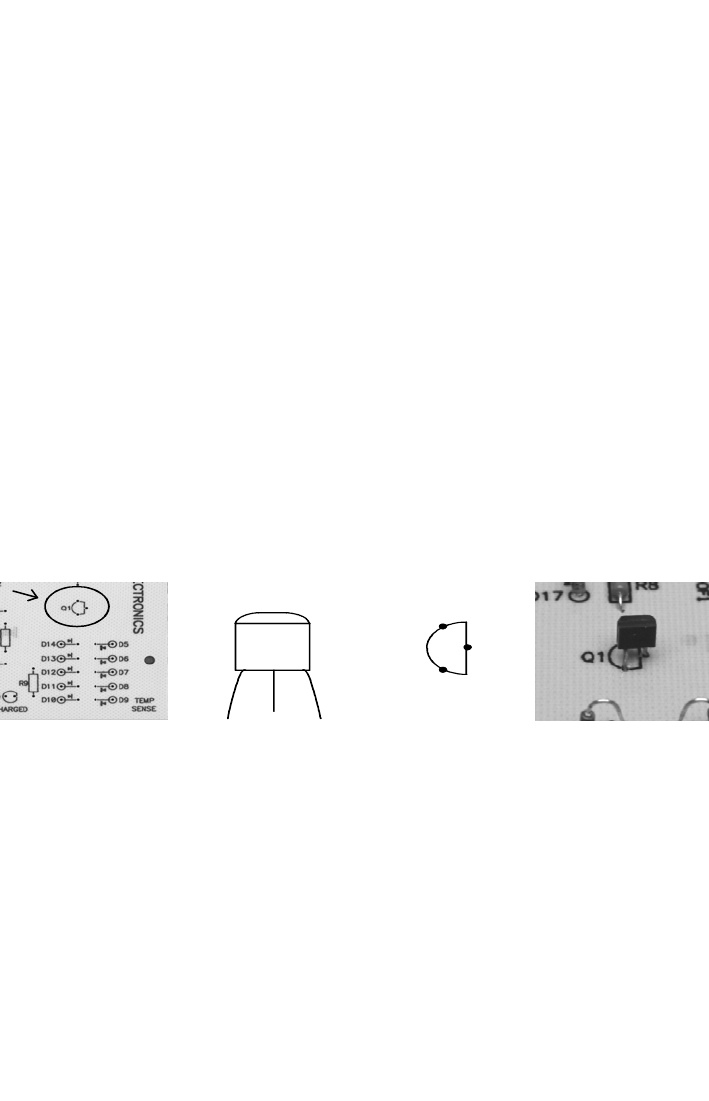
17. Install Q1, the 221334 PNP transistor. This transistor appears to have
two flat sides, one with writing on it and a larger flat side without writing.
The pin orientation of Q1, the 2N3906 (221334) transistor, is incorrect on
your LABC1 circuit board The larger flat side with no writing is the one
pictured on the silkscreen; orient the part using this as the correct flat side.
with the flat side (no writing) facing the front of the board towards the D5-
D14 diode matrix. Solder all three pins.
18. Install R1, 270 ohms (red-violet-brown).
19. Install the last jumper wire, JMP1. Form and solder as you did the
other jumpers. You can start throwing away your clipped off leads now!
20. Install R4, 18k ohms (brown-gray-orange).
You’ll see a designation on the silkscreen for R5. Now that I’ve brought it to
your attention, ignore it. This part is not needed for your LABC1.
21. Install R7, 820 ohms (gray-red-brown).
22. Install R9, the last 820 ohm resistor (gray-red-brown).
Next we’ll install a group of identical parts, the diodes D5 through D14. They
all must be installed in the correct polarity but if you can get the first one in
E
C
B
Q1
EB
C
221334
on back
Q1
E
C
B