


If this equipment does cause harmful interference to radio or television reception, which
can be determined by turning the equipment off and on, the user is encouraged to try to
correct the interference by one or more of the following measures:
• Reorient or relocate the receiving antenna.
• Increase the separation between the equipment and receiver.
• Connect the equipment into an outlet on a circuit different from that to which the
receiver is connected.
• Consult the dealer or an experienced radio/TV technician for help.
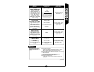
• Fixture must be connected to a 120 Volt, 60 Hz power source. Any other connection
voids warranty.
• Total wattage of light bulbs connected to the motion detector cannot exceed 300 watts
incandescent.
• This motion detector should be installed by persons with experience in household wiring
or by a qualified electrician. The electrical system, and the method of electrically connect-
ing the fixture to it, must be in accordance with the National Electrical Code and local
building codes.
• For proper operation and protection against damage, the motion sensor head adjustment
knobs must be facing the ground.
• Disassembly of your detector will void the warranty.
SAVE THESE INSTRUCTIONS.
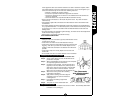
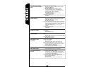
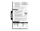
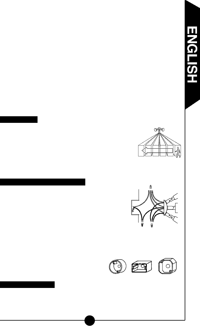
For best results
• Install your fixture 8-12 feet above ground (motion detector is less
sensitive above 12 feet).
• Locate fixture so motion moves across detection zone (D).
• Locate fixture away from heat producing sources to prevent false
triggering. Also be very careful not to include objects such as
windows, white walls and water in the detection zone whenever
possible.
• Locate fixture away from moving objects such as trees and
street traffic.
• Do not install more than one motion detector on one wall switch.
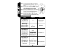
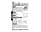
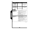
Assembling and wiring your motion detector
Step 1: Turn off the power at the main fuse/breaker box.
Step 2: Screw motion detector arm into the desired hole on
junction box coverplate.
Step 3: Attach all lampholders or light fixtures to the coverplate
as required by light fixture instructions.
Step 4: Connect the wires together. Connect all white wires
together (house wire, detector wire, and lamp fixture
white wires) using wire nuts provided. Connect black
lamp wires to red wire from the detector. Connect
black house wire to black wire from the detector (E).
Step 5: Attach fixture to the junction box according
to light fixture instructions.
Step 6: Apply silicone caulking around the edges of
coverplate and in any open screw holes for
a watertight seal.
Step 7: Insert bulb(s) according to light fixture
instructions.
Step 8: Turn power on at main fuse/breaker box.
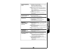
How to operate your fixture
Step 1: Move slide switch on bottom of the sensor to “TEST”. Set sensitivity slide switch
to medium or “M” (halfway) (F).
3
D
E
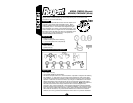
Round Rectangular (horizontal) Octagonal
Your fixture mounts
to the following standard
junction boxes: