


Assembly Instructions
WARNING
To prevent serious injury, proper assembly of the
Pipe Cutter is required. The following procedures
should be followed:
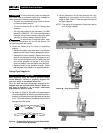
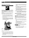
1. Connecting the hydraulic foot pump to the cutter.
a. Insert the male end of the quick-disconnect cou-
pling into the female end located on the hydraulic
cylinder (Figure 3).
b. The foot pump relief valve must be depressed to
release any line pressure and allow insertion of
the quick connector.
Failure to secure the power drive with the
reaction arm will result in the rotation of the power drive.
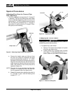
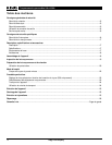
2. Connecting the 700 Power Drive to the cutter.
a. Push 774 Square Drive Adapter, spline end first,
squarely into power drive face gear until spring
loaded adapter pawls catch securely (Figure 4).
Ridge Tool Company 5
258/258XL Power Pipe Cutters
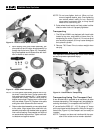
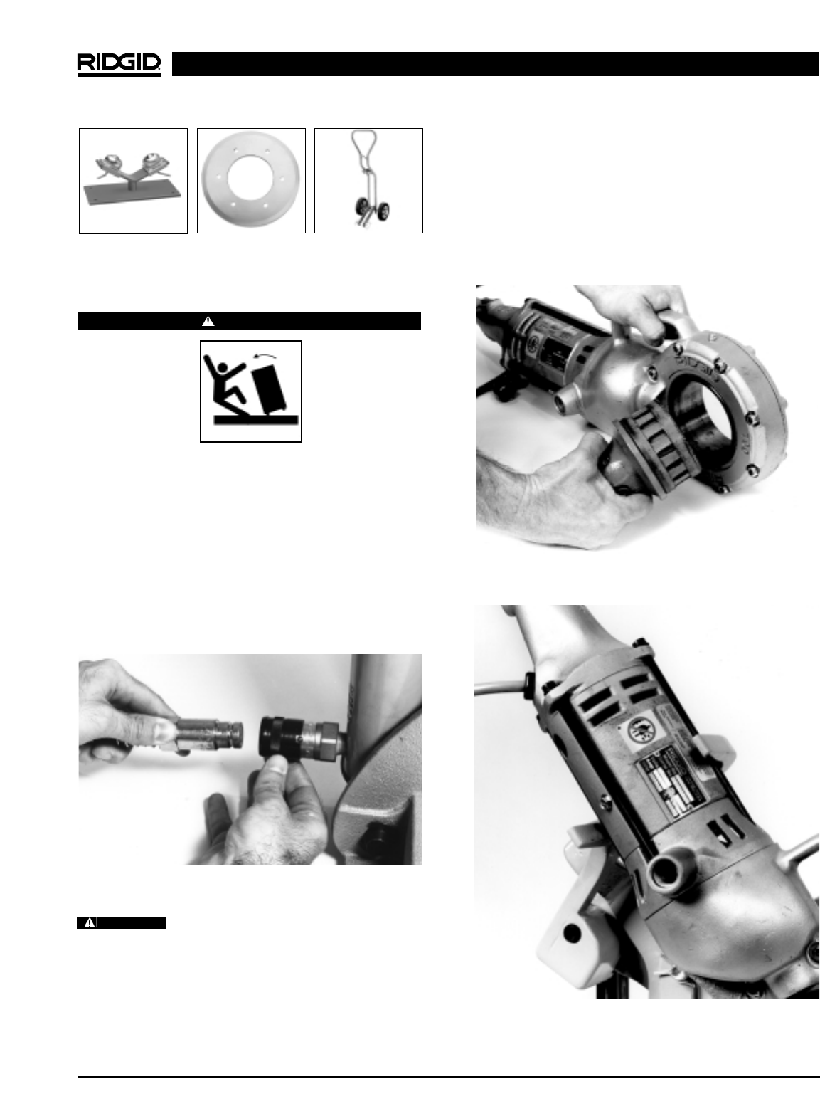
b. Place power drive with adapter on the cutter.
Power drive and adapter connect to the square
drive on the cutter. Be sure power drive rests
inside the reaction arm at the rear of the cutter
(Figure 5).
c. Hand tighten the two set screws on the 774
square drive adapter to the square drive with
5
/
16
″ allen wrench. (Provided with adapter.)
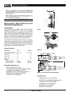
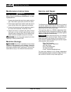
Ball Transfer Head
Cutter Wheel Transport Cart
Figure 3 – Connecting Hydraulic Foot Pump to Cutter
Figure 4 – Installing 774 Drive Adapter
WARNING
Figure 5 – Position Power Drive Inside Reaction Arm