


6
ASSEMBLY
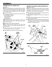
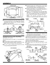
ASSEMBLING THE LOWER FOOT
See Figure 1.
NOTE: Only ONE spring pin is required at the carry handle
end of the stand. This spring pin locks the legs in the set-up
or tear-down position. Instructions to change the location
of this spring pin are described later in the “Assembly”
section of this manual.
n From carton, and bag of loose parts remove the following:
Hex Bolt, M6 x 41mm (2)
Curved Washers, M6 (4)
Lock Nuts, M6 (2)
Lower Foot (1)
Stand Assembly (1)
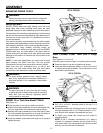
NOTE: Additional tools may be required to attach your
power tool to the stand. See “Mounting Power Tools”
section of this manual.
n Slide lower foot into the stand assembly.
NOTE: A dimple has been placed on one side of the
workstand frame to aid in proper assembly alignment of
the foot as shown.
n Attach the lower foot on each side with a hex bolt,
curved washers, and a lock nut as shown.
n Firmly tighten the nuts with two 10 mm wrenches.
Fig. 1
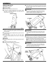
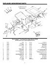
MOVING THE CARRY HANDLE SPRING PIN
See Figures 2 and 3.
NOTE: Only ONE spring pin is required to lock the legs in
the set-up or tear-down position. The spring pin can be
assembled on either side of the carry handle. To change
this location, follow the instructions below:
n Note how the spring and washer are assembled before
relocating them to the other side.
n Hold washer and spring with thumb and forefinger as
shown.
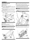
n Using a flat screwdriver pry the e-clip off the groove in
the end of the knob shaft.
n Reassemble the spring pin, washers and spring to the
other side. The knob must be to the inside. Reassemble
the washer, spring and e-clip on the end of the shaft
away from the knob as shown.
Fig. 2
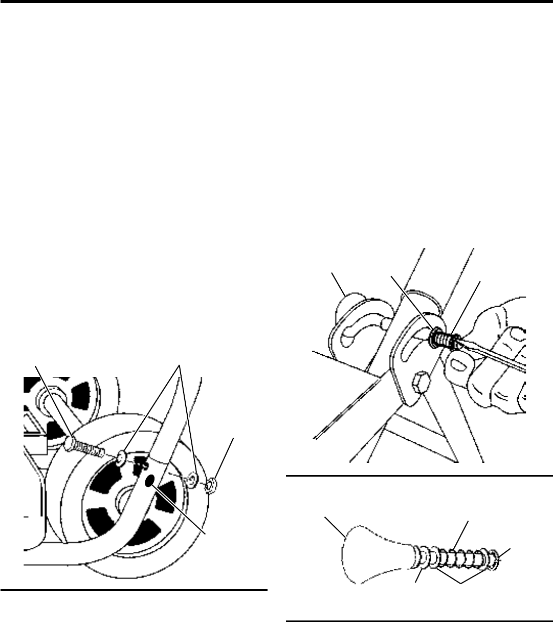
Fig. 3
CURVED
WASHER
LOCK NUT
DIMPLE IN
FRAME
HEX
BOLT
NYLON
WASHER
SPRING
KNOB
NYLON
WASHER
SPRING
KNOB
STEEL
WASHER
E-CLIP