6
Fig. 3
ASSEMBLY
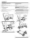
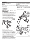
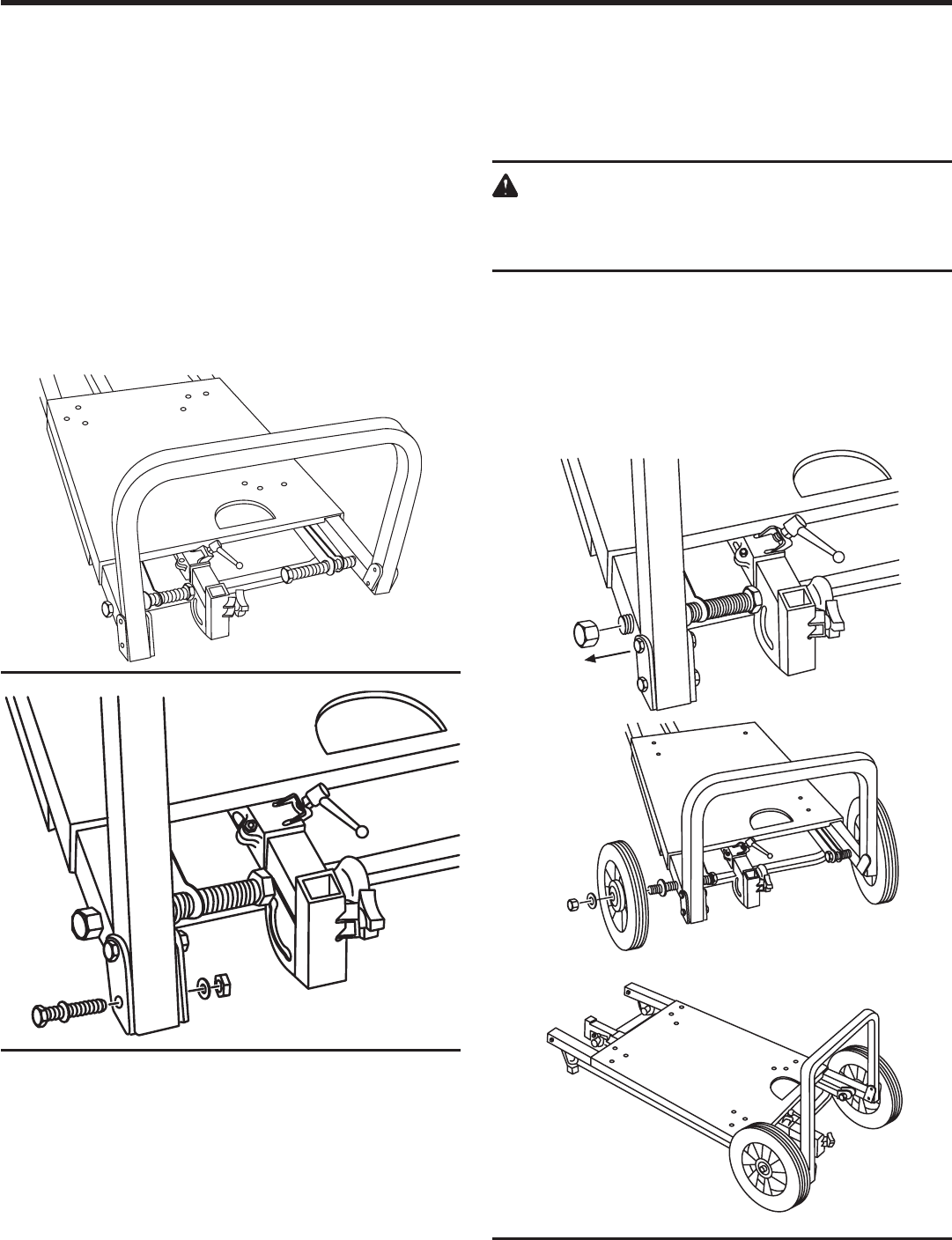
ATTACHING THE LOWER FOOT
See Figures 1 and 2.
n Place stand assembly “flat” on floor.
n Rotate lower foot into upright position aligning holes as
shown.
n Locate the following parts:
Hex Bolt, M8 x 50 mm (2)
Flat Washer, M8 (4)
Lock Nut, M8 (2)
n Install bolt, two washers and lock nut as shown. Finger
tighten lock nut.
n Repeat above step on the opposite side.
n Tighten all four lock nuts.
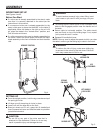
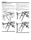
MOUNTING WHEELS
See Figure 3.
n Slide axle bolt outwards until it extends beyond the
frame.
n Remove axle lock nut and one washer.
WARNING:
Do not remove axle bolt(s) from the frame.
Energy from gas spring can cause injury if leg is
disconnected from axle bolt(s).
n Place wheel on axle bolt as shown
n Replace axle lock nut and washer as shown. Tighten
lock nuts securely. Check to see that the wheel freely
spins. If not, slightly loosen axle lock nut. Repeat steps
above steps for opposite wheel.
n Press plastic cap over each wheel lock nut by gently
tapping with a hammer.
Fig. 1
Fig. 2
OUTWARDS


