


12
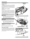
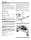
TO INSTALL/CHANGE SANDING BELT
See Figures 5 - 6.
n Unplug the sander.
n Position sander as shown.
WARNING:
Keep hands and fingers clear of front roller and
spring mechanism at all times. Failure to do so
could result in fingers getting pinched, causing
possible serious injury.
Belt tension must be released in order to install and remove
sanding belt:
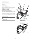
n Release belt tension by lifting tension release lever.
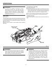
n Install sanding belt; make sure arrow inside of belt is
pointing in the direction of rotation, which is clockwise
when looking into open side of sander.
NOTE: Match the arrow on the sanding belt to that of the
housing.
CAUTION:
If the sanding belt is not a bidirectional belt,
ensure that the arrow inside the belt is pointing
in the direction of the rotation (clockwise when
looking into the open side of the sander). Installing
unidirectional sanding belts backwards can create
a hazardous condition.
n Align the sanding belt to its correct position.
n Lower tension release lever to secure the sanding belt.
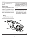
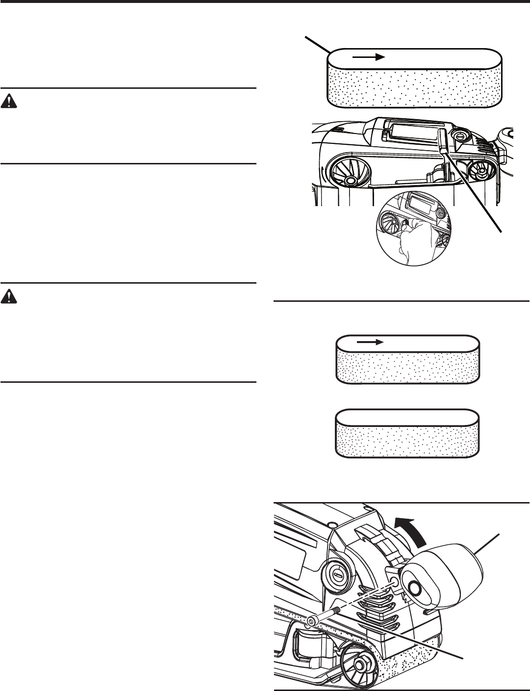
TO ADJUST FRONT HANDLE
See Figure 7.
n Unplug the belt sander.
n Remove the supplied hex key from hex key storage.
n Using hex key, remove hex bolt located on front han-
dle.
n Move front handle to desired position aligning notch in
handle mount on tool with hex bolt hole in handle, insert
hex bolt and retighten front handle using hex key.
n Return hex key to hex key storage area located on the
rear handle bridge.
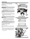
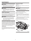
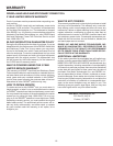
SANDING BELTS WITH DIRECTION OF ROTATION
ARROWS MUST BE INSTALLED CORRECTLY
SANDING BELTS WITHOUT DIRECTION OF ROTATION
ARROWS CAN BE USED IN EITHER DIRECTION
BELT TENSION
RELEASE
LEVER
SANDING
BELT
LIFT BELT TENSION RELEASE LEVER
TO REMOVE SANDING BELT
LOWER BELT TENSION RELEASE
LEVER TO SECURE SANDING BELT
OPERATION
Fig. 5
Fig. 6
Fig. 7
HEX BOLT
FRONT
HANDLE