


12
13
OPERATION
Fig. 8
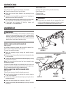
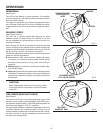
REVERSIBLE
See Figure 7.
The drill has the feature of being reversible. The direction
of chuck rotation is controlled by a switch located on either
side of the drill housing.
The design of the switch will not permit changing the direc-
tion of rotation while the drill is running. Release the switch
trigger and allow the drill to stop before changing its direc-
tion.
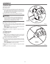
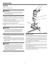
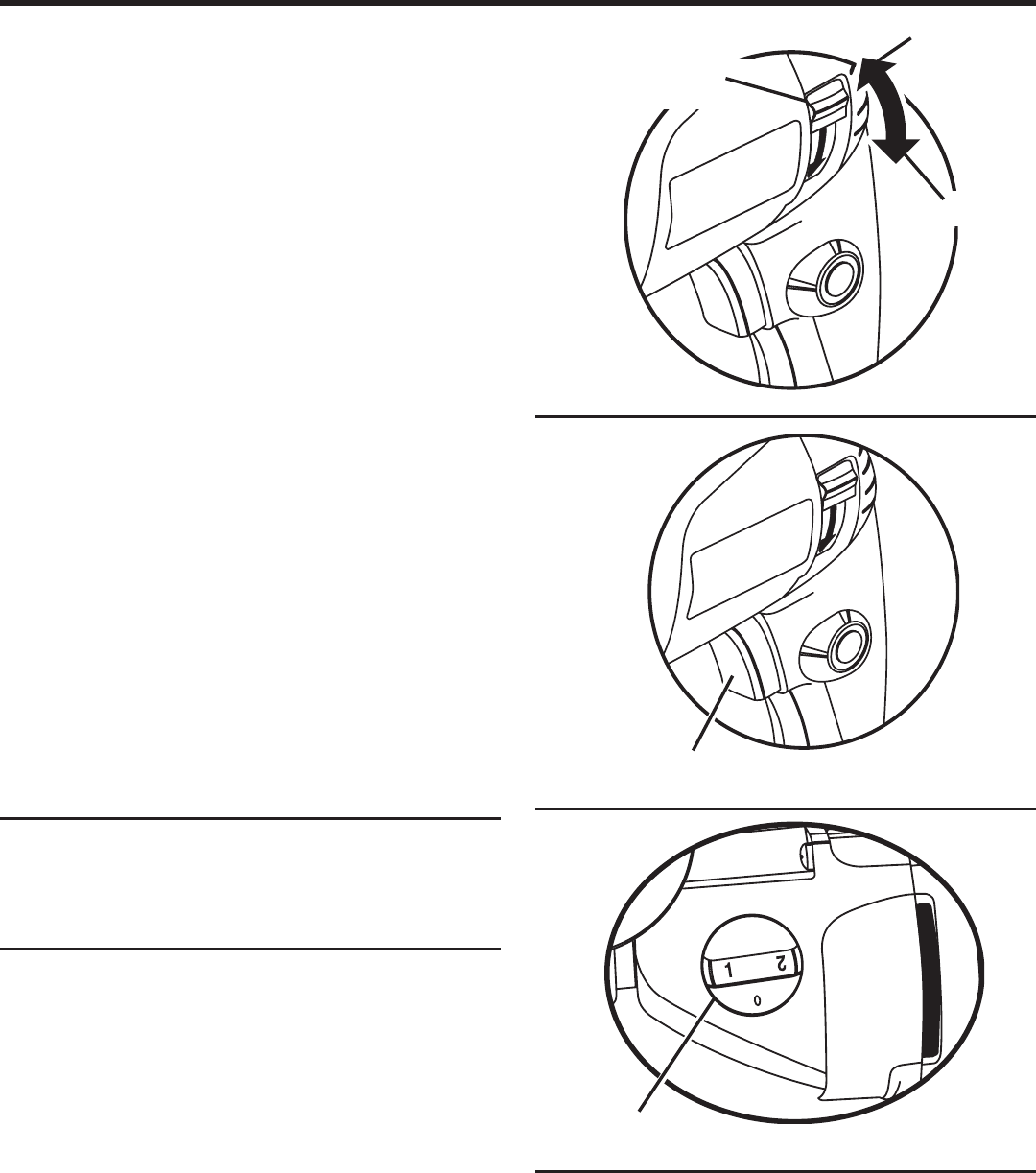
VARIABLE SPEED
See Figures 8 and 12.
The drill has a variable speed dial designed to allow
operator control of speed limits. The speed of the drill
can be increased by turning the dial on top of the drill in a
clockwise direction.
Avoid running the drill at low speeds for extended periods
of time. Running at low speeds under constant usage may
cause the drill to become overheated. If this occurs, cool the
drill by running it without a load and at full speed.
The following guidelines may be used in determining correct
speed for various applications:
n Low speed is ideal when minimum speed and power
is required. For example, starting holes without center
punching, driving screws, mixing paint, and drilling in
ceramics.
n Medium speed is suitable for drilling hard metals, plas-
tics, and laminates.
n High speed produces best results when maximum power
is required. For example, drilling in wood; soft metals such
as aluminum, brass, and copper, and when using driving
accessories.
CAUTION:
Never change gears while the tool is running. Failure
to obey this caution could result in serious damage
to the drill.
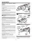
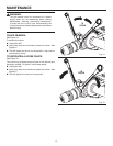
TWO-SPEED GEAR SHIFT KNOB
See Figure 9.
The hammer drill has a two-speed gear shift knob which
provides a high speed of approximately 3,000 RPM and a
low speed of approximately 1,000 RPM (stated speeds are
with the switch trigger in “Full-On” position).
For high speed operation, rotate two-speed gear shift knob
clockwise aligning with indicating mark on knob. For low
speed operation, rotate knob counterclockwise with indicat-
ing mark on knob. It may be necessary to rotate the chuck
by hand while rotating knob.
Fig. 9
Fig. 7
TO INCREASE SPEED,
PULL SWITCH TRIGGER
FORWARD-REVERSE
CENTER LOCK OFF
LEVER
REVERSE
FORWARD
TWO-SPEED
GEAR SHIFT KNOB