


12
OPERATION
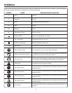
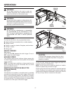
Fig. 6
TWO-SPEED
GEAR SHIFT KNOB
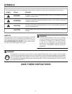
RIGHT
Fig. 7
WRONG
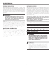
Fig. 8
DRILL BIT
TO TIGHTEN
CHUCK JAWS
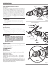
TWO-SPEED GEAR SHIFT KNOB
See Figure 6.
The drill has a two-speed gear train designed for drilling or
driving at LO (1) or HI (2) speeds. A switch is located on the
side of the drill to select either LO (1) or HI (2) speed. When
using drill in the LO (1) speed range, speed will decrease
and unit will have more power and torque. When using drill in
the HI (2) speed range, speed will increase and unit will have
less power and torque. Use LO (1) speed for high power
and torque applications and HI (2) speed for fast drilling or
driving applications.
CAUTION:
Never change gears while the tool is running. Failure
to obey this caution could result in serious damage
to the drill.
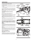
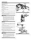
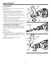
TO INSTALL BITS
See Figures 7 - 8.
Unplug the drill.
Insert the chuck key and twist counterclockwise.
Open or close the chuck jaws to a point where the opening
is slightly larger than the bit size you intend to use. Also,
raise the front of the drill slightly to keep the bit from falling
out of the chuck jaws.
WARNING:
Make sure to insert the drill bit straight into the
chuck jaws. Do not insert the drill bit into the chuck
jaws at an angle then tighten, as shown in figure 8.
This could cause the drill bit to be thrown from the
drill, resulting in possible serious personal injury or
damage to the chuck.
Insert the drill bit.
Tighten the chuck jaws securely on the drill bit, using the
chuck key provided.
Remove the chuck key.
TO REMOVE BITS
See Figure 7.
Unplug the drill.
Loosen the chuck jaws using the chuck key provided.
Remove the drill bit.
Remove the chuck key.
TO LOOSEN
CHUCK
KEY
CHUCK
CHUCK KEY STORAGE
LO (1)
HI (2)
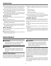
USING THE AUXILIARY HANDLE ASSEMBLY
See Figure 9.
An auxiliary handle assembly is packed with the drill for
ease of operation and to help prevent loss of control. The
handle can be rotated 360°, and it can also be mounted on
the opposite side for left hand use.