


15
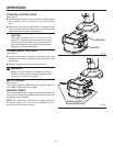
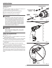
PULL COUPLER
FORWARD
Fig. 10
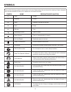
OPERATION
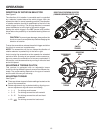
BIT
1
2
3
INSERT BIT
RELEASE COUPLER
COUPLER
LOCKING
GROOVE
Fig. 11
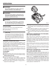
REMOVING BITS
See Figure 10.
n Lock the switch trigger by placing the direction of
rotation selector in the center position.
n Remove the battery pack from the screwdriver.
n Pull the coupler away from the screwdriver.
n Remove screwdriver bit from the coupler.
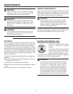
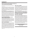
WARNING:
Do not drive a screw where there is likely to be
hidden wiring behind the surface. Contact with a
“live” wire will make exposed metal parts of the tool
“live” and shock the operator. If you must drive a
screw where hidden wire may be present, always
hold tool by insulated gripping surfaces (handle)
when performing the operation to prevent a shock
to the operator, as seen in figure 11.
CAUTION:
Gear housing may become warm to the touch
while screwdriver is operating. Do not use as a
gripping surface.
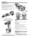
USING THE SCREWDRIVER
See Figures 11 - 12.
n Check the direction of rotation selector for the correct
setting (forward or reverse).�
n Secure the material to be driven in a vise or with clamps
to keep it from turning as the screwdriver bit rotates.�
n Hold the screwdriver firmly and place the bit at the point
to be driven.�
n Depress the switch trigger to start the screwdriver.
n Move the screwdriver bit toward the workpiece. Do not
force the screwdriver. Let the tool do the work.
NOTE: This drill has an electric brake. When the switch trig-
ger is released, the chuck stops turning. When the brake is
functioning properly, sparks will be visible through the vent
slots on the housing. This is normal and is the action of the
brake.
Fig. 12
WRONG
RIGHT