14
ASSEMBLY
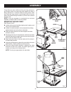
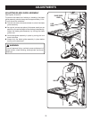
SQUARING THE SAW TABLE TO THE BLADE
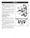
See Figure 8.
Turn the lock knob counterclockwise to unlock the blade
guide assembly. Turning the blade guide knob clockwise,
raise the blade guide assembly as far as it will go. Turn
the lock knob clockwise to retighten.
Place a small combination square on the saw table beside
the blade.
Loosen the table lock knob and rotate the angle
adjustment knob to tilt the saw table up or down to align
table 90° to blade (0° position). Retighten the table lock
knob.
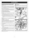
Using a 4 mm hex key, adjust the zero stop set screw
until the set screw just touches the saw housing.
Check squareness of the saw table to the blade. Make
readjustments if necessary.
Loosen screw on scale indicator with a phillips screwdriver
and align scale indicator to zero.
Tighten all screws securely.
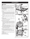
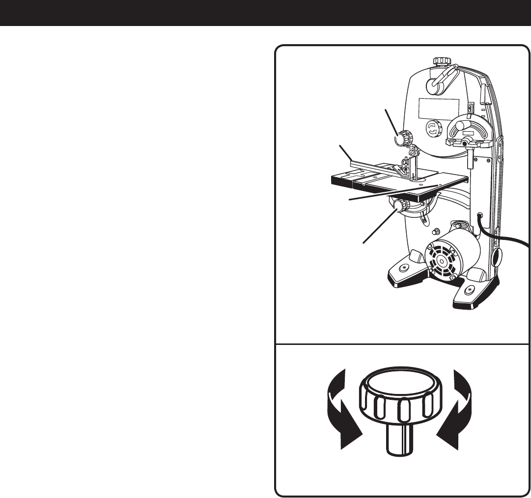
ADJUSTING BLADE TENSION
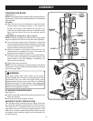
See Figures 9 and 10.
Remove the switch key.
Before using the band saw, turn the blade tension knob
on the top of the saw clockwise to engage tension.
NOTE: Adjustments of blade tension can be made at
anytime.
Another method of checking blade tension has to do with the
sound the blade makes when plucked like a guitar string.
Pluck the back straight edge on the coasting side
opposite the blade guides while turning the tension knob.
Sound should be a musical note. Sound becomes higher
pitched as tension increases.
Using either method to check blade tension can be devel-
oped with practice.
Never increase blade tension so tight as to completely
compress the spring. When completely compressed, the
spring can no longer act as a shock absorber.
NOTE: Too much tension may cause the blade to break. Too
little tension may cause the blade to slip on the wheels.
Fig. 8
LOCK
KNOB
SMALL
COMBINATION
SQUARE
ZERO STOP
SET SCREW
Fig. 9
BLADE TENSION KNOB
TO INCREASE
TENSION
TO DECREASE
TENSION
TABLE LOCK
KNOB


