


10
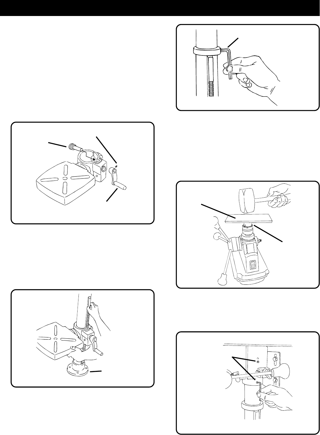
Fig. 6
Fig. 7
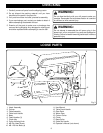
ASSEMBLY
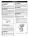
TOOLS NEEDED FOR ASSEMBLY
#1 and #2 Philips Screwdriver
Adjustable Wrench
Hammer or rubber mallet
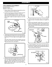
1. Place the base on a flat surface and assemble the column
to the base using the four M8 hex bolts.
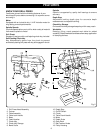
2. Locate the worm gear and feed the D-shaft through the
hole in the table assembly as shown in Figure 4.
Insert the D-shaft through the hole in the table crank.
Align flat side of shaft with the set screw on the table
crank handle. Tighten set screw using the 4 mm hex
wrench.
3. Feed the gear rack through the slot in the table assembly
so that the teeth are facing out and the longer smooth
end faces up. The worm gear should engage the gear
rack.
Using both hands, slide the entire assembly onto the
column until the bottom of the gear rack is positioned
against the base collar.
See Figure 5.
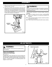
5. Locate the table lock handle. Insert it into the threaded
hole at the rear of the table assembly and tighten by
hand.
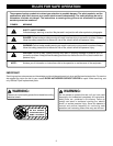
6. Position head assembly upside down on a level, flat
surface. Position chuck on spindle. Chuck should be fully
opened to avoid damaging jaws. Using a piece of scrap
wood to protect the chuck, firmly tap the chuck into place
using a hammer.
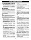
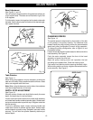
7. Lift head assembly onto column with the spindle
positioned over the table. Slide head assembly down as
far as it will go. Tighten the two head set screws with the
4 mm hex wrench.
See Figure 8.
WORM
GEAR
Fig. 4
SET SCREW
TABLE CRANK HANDLE
SET SCREW
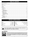
BASE COLLAR
WOOD SCRAP
CHUCK
Fig. 5
4. Slide the column collar, bevel side down, over the column
until the beveled side engages the beveled end of the
gear rack. Tighten the set screw in the collar using the
4 mm hex wrench.
See Figure 6.
Do not overtighten.
NOTE: Table should be able to move side to side. Do
not overtighten set screw.
Fig. 8
SET SCREWS