


12
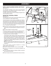
LOOSE PARTS
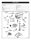
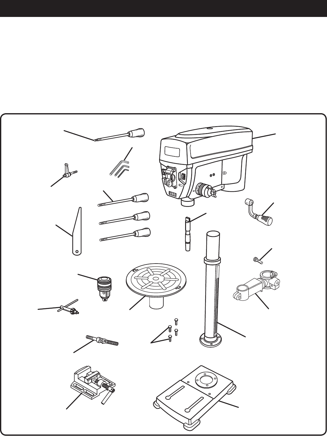
Fig. 4
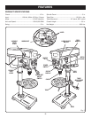
The following items are included with the drill press:
Head Assembly .................................................................1
Column Assembly .............................................................1
Table ..................................................................................1
Table Support ....................................................................1
Base ..................................................................................1
Hex Key (3 mm, 4 mm, and 5 mm) ....................................3
Hex Bolts (M8) ...................................................................4
Feed Handles ....................................................................3
Worm Gear ........................................................................1
Spindle Lock Lever ............................................................1
Table Adjustment Handle ..................................................1
Table Lock Handle .............................................................1
Variable Speed Lever ........................................................1
Chuck Tool.........................................................................1
Chuck ................................................................................1
Chuck Key .........................................................................1
Vise ....................................................................................1
Operator’s Manual (not shown) .........................................1
chuck tool
head
assembly
table
adjustment
handle
table suPPort
table
sPindle
hex key (3)
feed
handles
(3)
chuck
chuck
key
table lock
handle
Vise
base
column
assembly
hex
bolts
worm
Gear
Variable sPeed
leVer
sPindle
lock
leVer