


17
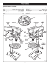
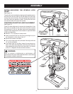
ASSEMBLY
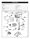
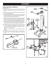
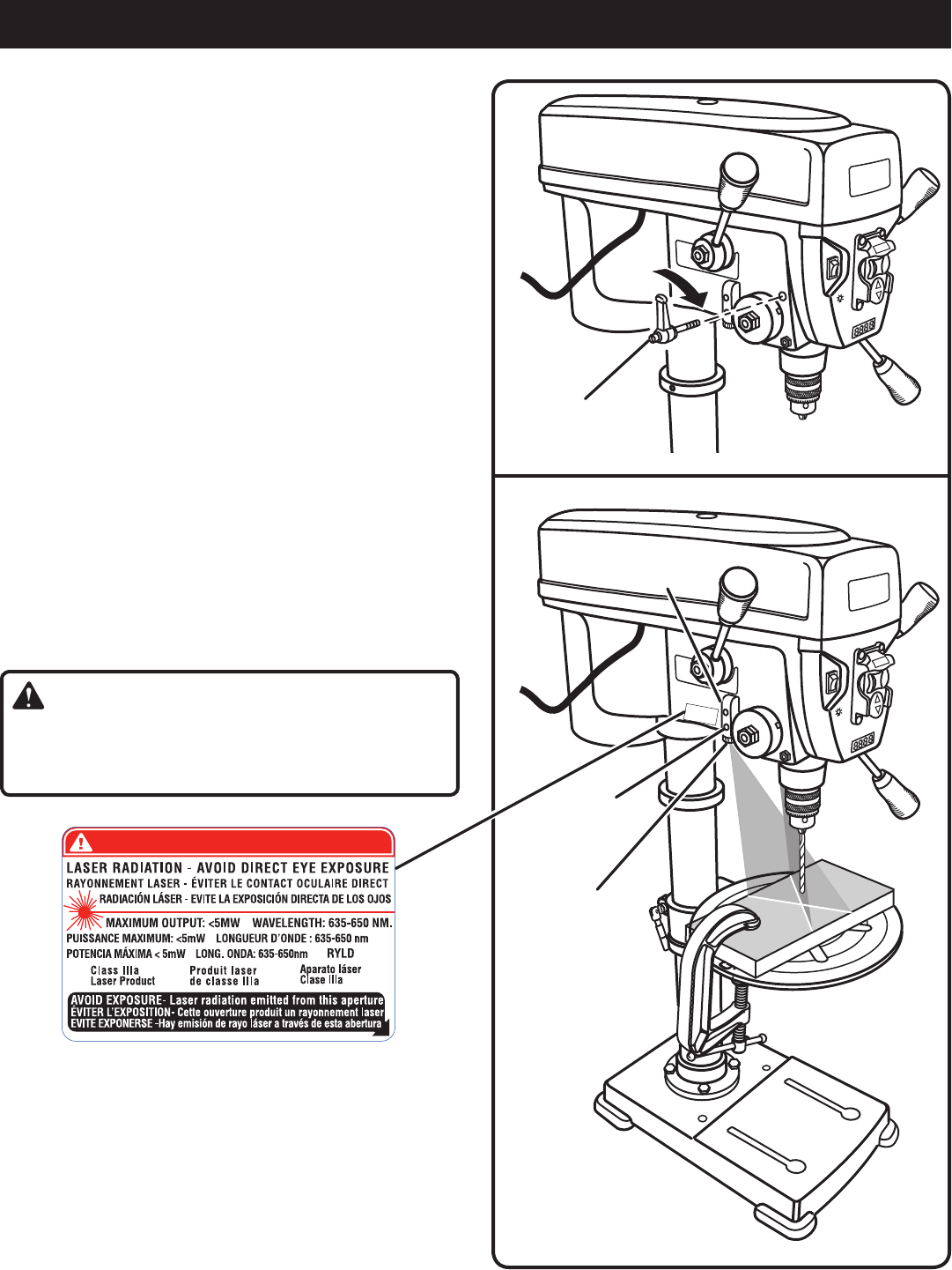
laser
adjustment
knob
laser
housinG
set
screw
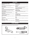
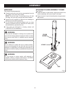
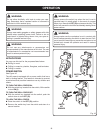
INSTALLING/USING THE SPINDLE LOCK
LEVER
See Figure 14.
The spindle lock is installed by aligning the threaded post on
the lock lever with the hole on the left side of the tool then
turning the post clockwise. Securely tightening the spindle
lock lever locks the spindle in place. Turning the lock lever
counterclockwise will loosen the spindle.
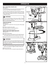
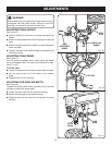
CHECKING/ADJUSTING LASER ALIGNMENT
See Figure 15.
Check the laser alignment to ensure the intersection of the
laser lines is precisely at the spot where the drill bit meets
the workpiece. If it is not, the laser lines should be adjusted
using the laser adjustment knobs located on opposite sides
of the head assembly.
Mark an “X” on a piece of scrap wood.
Insert a small drill bit into the chuck and align its tip to
the intersection of the lines of the “X”.
Secure the board to the table.
Turn on the laser and verify the laser lines align with the
“X” on the workpiece.
If the laser lines do not align, loosen the set screws on
each of the laser housings with a hex key and rotate the
laser adjustment knobs until the lines meet in the center
of the “X”. Retighten the set screws to secure.
WARNING:
Use of controls or adjustments or performance of
procedures other than those specified herein could result
in hazardous radiation exposure.
Fig. 14
Fig. 15
turn clockwise
to install / lock
the sPindle
D
A
N
G
E
R
/
D
A
N
G
E
R
/
P
E
L
I
G
R
O
D
A
N
G
E
R
/
D
A
N
G
E
R
/
P
E
L
I
G
R
O