


Page 6
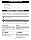
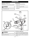
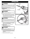
SWITCH
See Figure 2.
To turn your hammer drill ON, depress the switch trigger.
Release switch trigger to turn your hammer drill OFF.
LOCK-ON BUTTON
See Figure 2.
Your hammer drill is equipped with a "lock-on" feature, which
is convenient when continuous drilling for extended periods
of time is required. To lock-on, depress the switch trigger,
push in and hold the lock-on button located on the side of the
handle, then release switch trigger. Release lock-on button
and your drill will continue running.
To release the lock, depress the switch trigger and release
it.
If you have the "lock-on" feature engaged during use and
your drill becomes disconnected from power supply,
disengage the "lock-on" feature immediately.
WARNING:
Before connecting your hammer drill to power supply
source, always check to be sure it is not in “lock-on”
position (depress and release switch trigger). Failure to
do so could result in accidental starting of your drill
resulting in possible serious injury. Also, do not lock the
trigger on jobs where your drill may need to be stopped
suddenly.
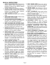
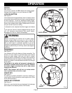
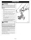
REVERSIBLE
See Figure 3.
Your hammer drill has the feature of being reversible. The
direction of chuck rotation is controlled by a lever located
above the switch trigger. With your drill held in normal
operating position, the direction of rotation lever should be
positioned to the left of the switch for drilling operation. The
direction of rotation is reversed when the lever is to the right
of the switch.
The design of the switch will not permit changing the
direction of rotation while the drill is running. Release
the switch trigger and allow the drill to stop before
changing its direction.
NOTE: Your hammer drill will not run unless switch
lever is pushed fully to the left or right.
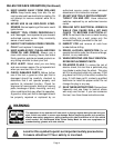
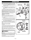
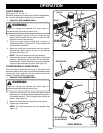
CHUCK KEY
See Figure 4.
A chuck key has been provided for use when installing or
removing bits. It is also used when removing the chuck. (See
chuck removal section).
CHUCK KEY STORAGE
See Figure 4.
When not in use, the chuck key can be placed in the storage
area located on the bottom portion of drill handle.
Fig. 4
OPERATION
Fig. 2
Fig. 3
LOCK-ON
BUTTON
SWITCH TRIGGER
FORWARD-REVERSE LEVER
REVERSE
FORWARD
CHUCK KEY
STORAGE
TO
REMOVE
TO
STORE