


Page 7
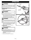
VARIABLE SPEED
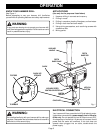
See Figure 5.
Your hammer drill has a variable speed control selector
designed to allow operator control and adjustment of speed
and torque limits. Speed and torque can be increased or
decreased by rotating the variable speed control selector in
the direction of the arrows shown in figure 5.
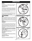
NOTE: Hold your hammer drill in normal operating position
and turn the variable speed control selector clockwise to
increase the speed and torque of your hammer drill. Turn
counterclockwise to decrease the speed and torque of your
hammer drill.
If you desire to lock the switch on at a given speed, depress
the switch trigger, push in and hold the lock-on button, and
release the switch trigger. Next, adjust the variable speed
control selector until the desired speed is reached.
NOTE: If the variable speed control selector is fully
turned in the counterclockwise direction (zero setting)
your drill may not run.
If you desire not to use the variable speed control
selector, turn it in the full clockwise direction. This will
allow the speed of your drill to be fully controlled by the
amount of switch trigger depression.
Avoid running your hammer drill at low speeds for extended
periods of time. Running at low speeds under constant usage
may cause your drill to become overheated. If this occurs,
cool your drill by running it without a load and at full speed.
The following guidelines may be used in determining correct
speed for various applications:
LOW speed is ideal when minimum speed and power is
required. For example: starting holes without center punch-
ing, driving screws, mixing paint, and drilling in ceramics.
MEDIUM speed is suitable for drilling hard metals, plastics,
and laminates.
HIGH speed produces best results when maximum power is
required. For example: drilling in wood; soft metals such as
aluminum, brass, and copper; and when using driving acces-
sories.
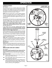
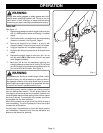
INSTALLING AUXILIARY HANDLE
See Figure 6.
An auxiliary handle is packed with your hammer drill for
ease of operation and to help prevent loss of control.
NOTE: For convenience the screw has been trapped inside
the auxiliary handle.
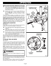
■ Remove depth gage clamp and auxiliary handle from
plastic bag in hammer drill box.
■ Orient depth gage clamp so that the tabs will fit into
motor housing of hammer drill.
■ Thread depth gage clamp onto auxiliary handle until it
reaches undercut area of screw threads. Undercut of
screw threads will keep depth gage clamp on auxiliary
handle, preventing it from getting lost.
Fig. 6
Fig. 5
OPERATION
VARIABLE SPEED
CONTROL SELECTOR
TO
INCREASE
SPEED
TO
DECREASE
SPEED
AUXILIARY
HANDLE
DEPTH
GAGE CLAMP
DEPTH
GAGE ROD
TABS
SLOTS
MOTOR
HOUSING