


Page 7
OPERATION
Fig. 1
Fig. 2
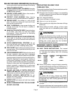
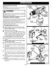
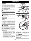
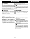
KNOW YOUR DRILL-DRIVER
See Figure 1.
Before attempting to use any tool, familiarize yourself with all
operating features and safety requirements.
WARNING:
Do not allow familiarity with tools to make you careless.
Remember that a careless fraction of a second is
sufficient to inflict severe injury.
CHARGING YOUR DRILL-DRIVER
The battery pack for this tool has been shipped in a low
charge condition to prevent possible problems. Therefore,
you should charge it at least 6 hours prior to use.
Note: Batteries will not reach full charge the first time they
are charged. Allow several cycles (drilling followed by re-
charging) for them to fully charge.
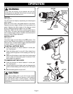
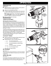
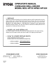
TO CHARGE MODEL NO. HP721
■ Charge battery pack only with the charger provided.
■ Make sure power supply is normal house voltage,
120 volts, 60 Hz, AC only.
■ Connect charger to power supply.
■ The charge indicator light (LED) indicator, which is
located on rear of battery pack, will light up when
charger is properly connected to power supply. This
red light indicates your drill is charging and will remain
on until charger is disconnected from power supply.
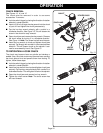
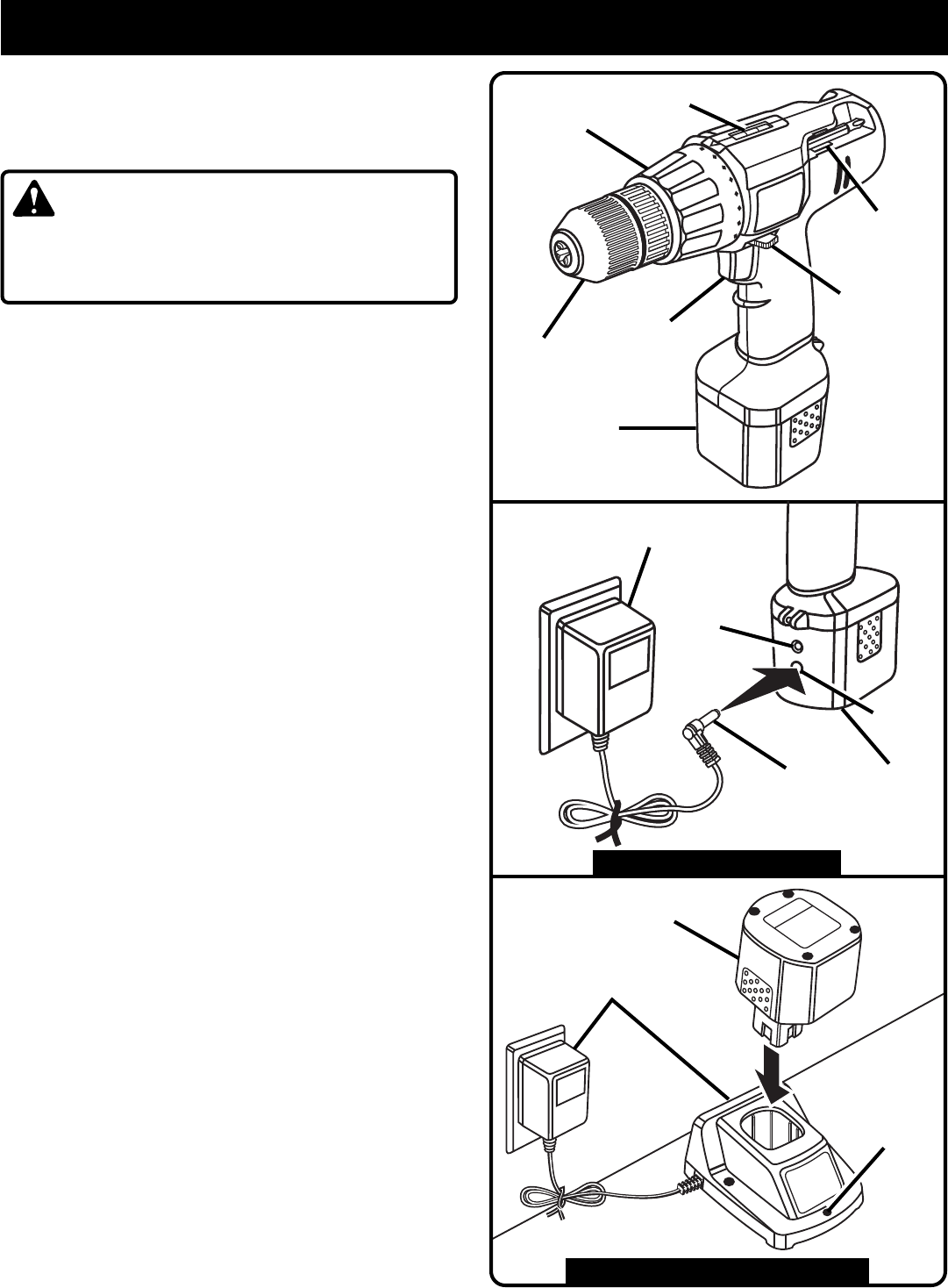
TO CHARGE MODEL NOS. HP961/HP1201
■ Charge battery pack only with the charging assembly
provided.
■ Make sure power supply is normal house voltage,
120 volts, 60 Hz, AC only.
■ Connect charging assembly to power supply.
■ Place battery pack in charging assembly. Align raised
rib on battery pack with groove in charging assembly.
See
Figure 3
.
■ Press down on battery pack to be sure contacts on
battery pack engage properly with contacts in charging
assembly. When properly connected, red light will turn
on.
■ After normal usage, 3 hours of charging time is re-
quired to be fully charged. A minimum charge time of 6
hours is required to recharge a completely discharged
battery.
■ The battery pack will become slightly warm to the touch
while charging. This is normal and does not indicate a
problem.
■ DO NOT place charging assembly in an area of ex-
treme heat or cold. It will work best at normal room
temperature.
Fig. 3
KEYLESS
CHUCK
BIT
STORAGE
AREA
TORQUE
ADJUSTMENT
RING
SWITCH
TRIGGER
1
3
5
7
9
TO CHARGE MODEL NO. HP721
BATTERY
CHARGER
CHARGING
ASSEMBLY
BATTERY
PACK
TO CHARGE MODEL NOS. HP961/HP1201
DIRECTION OF
ROTATION
SELECTOR
LEVEL
BATTERY
PACK
BATTERY
PACK
CHARGER
PLUG
INPUT
JACK
CHARGE
INDICATOR
LIGHT (LED)
CHARGE
INDICATOR
LIGHT (LED)