16
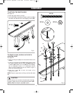
MOUNTING THE ROUTER
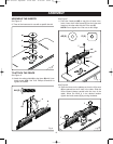
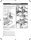
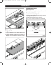
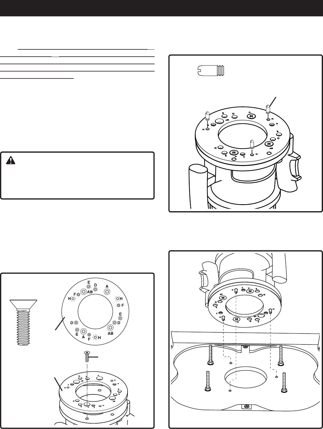
See Figure 16
6. Screw the three locating pins (Y) into nuts on adapter
plate from top side at hole position H.
Y
Y (3)
Fig. 16
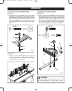
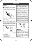
Fig. 17
See Figure17
7. Turn the router table upside-down. Align the three
locating pins in the bottom of the table top as shown.
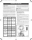
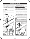
Fig. 15
III. Mounting Routers with the universal
clamping system
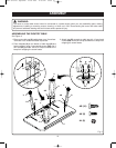
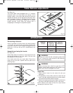
Note: All routers will require using the adapter plate (F)
and locating pins (Y) when mounting the router to the
router table with the universal clamping system. Refer to
Hole Pattern Chart on page 14 to determine the correct
hole pattern for your router.
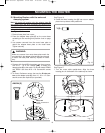
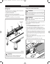
See Figure 15
1. Remove base plate from router.
2. Place the adapter base plate (F) on the router base
according to the mounting hole position chart on page
14.
3. Use screws removed from the router base plate to
attach the adapter base plate to the router base.
Tighten securely.
AM/AN (3)
WARNING:
Make sure screws from router base plate match the
countersinks in the adapter plate and are long enough
to attach the base plate securely. Replace if neces-
sary.
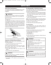
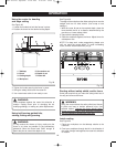
4. Routers with A and AB hole pattern use three counter-
sink 5/16" - 18 X 3/4" screws (AM), to attach the
adapter plate (F) to the router. For Ryobi routers RE600
and RE601 use three M 8 x 20 countersink screws
(AN).
5. To mount Craftsman routers that use the E-hole pat-
tern to the adapter plate (F), three 10 - 32 x 1/2" coun-
tersink screws are required (not provided).
F
F
AM or AN
NOTE: Countersink
screws
Bdal 6146.461 3Sprachen 04.06.2005 11:58 Uhr Seite 16


