


Page 10
4545
5050
3
0
30
2222
1
1
2
3
0
45
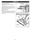
WARNING:
Always remove battery pack from your saw when you
are assembling parts, making adjustments, assembling
or removing blades, cleaning, or when not in use. Re-
moving battery pack will prevent accidental starting that
could cause serious personal injury.
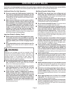
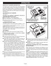
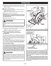
TO REMOVE BATTERY PACK
■ Locate latches on side of battery pack and depress to
release battery pack from your saw.
See Figure 4.
■ Remove battery pack from your saw.
WARNING:
Failure to remove battery pack from saw could result in
accidental starting causing possible serious personal
injury.
TO INSTALL BATTERY PACK
See Figure 4.
■ Place battery pack in your saw. Align raised rib on
battery pack with groove in saw.
■ Make sure the latches on each side of your battery pack
snap in place and battery pack is secured in saw before
beginning operation.
CAUTION:
When placing battery pack in your saw, be sure raised rib
on battery pack aligns with groove inside saw and latches
snap into place properly. Improper assembly of battery
pack can cause damage to internal components.
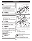
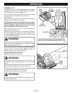
WARNING:
A 5-1/2 in. (140 mm) blade is the maximum blade capac-
ity of your saw. Never use a blade that is too thick to
allow outer blade washer to engage with the flats on the
spindle. Larger blades will come in contact with the blade
guard, while thicker blades will prevent blade screw from
securing blade on spindle. Either of these situations could
result in a serious accident.
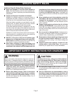
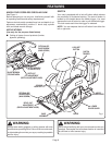
TO ASSEMBLE OR REMOVE BLADE
TO ASSEMBLE BLADE:
■ Remove battery pack from saw.
WARNING:
Failure to remove battery pack from saw could result in
accidental starting causing possible serious personal injury.
454
5
5050
303
0
222
2
1
1
2
3
0
45
BATTERY
PACK
LATCHES
DEPRESS LATCHES TO
RELEASE BATTERY PACK
BLADE
LOWER
BLADE
GUARD
HANDLE
SPINDLE
OUTER
BLADE
WASHER
INNER
BLADE
WASHER
Fig. 5
Fig. 4
■ Locate latches on side of battery pack and depress to re-
lease battery pack from your saw.
See Figure 4.
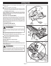
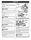
■ Remove blade wrench (5 mm hex key) from storage area.
See Figure 1.
■ Depress spindle lock button and remove blade screw and
outer blade washer.
See Figure 5.
NOTE: Turn blade screw clockwise to remove.
■ Wipe a drop of oil onto inner blade washer and outer blade
washer where they contact blade.
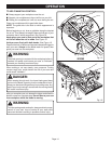
WARNING:
If inner blade washer has been removed, replace it be-
fore placing blade on spindle. Failure to do so could cause
an accident since blade will not tighten properly.
SPINDLE
LOCK
BUTTON
BLADE
SCREW
OPERATION