


Page 8
ADJUSTMENTS
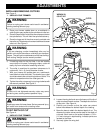
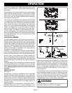
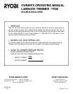
INSTALLING/REMOVING CUTTERS
See Figure 3.
1. UNPLUG YOUR TRIMMER.
WARNING:
Failure to unplug your trimmer could result in accidental
starting causing serious injury.
2. Place your trimmer upside down on a workbench in
order to gain easy access to the spindle and collet nut.
3. Place the small end of one of the wrenches provided on
the spindle flats. This will hold the spindle stationary.
4. Place the large end of the other wrench provided onto
the collet nut. Rotate wrench counterclockwise to loosen
collet nut.
See Figure 3.
WARNING:
If you are changing a cutter immediately after use, be
careful not to touch the cutter or collet with your hands or
fingers. They will get burned because of the heat buildup
from cutting. Always use the wrench provided.
5. If installing cutter for the first time, it can be installed
once collet nut is loose. If changing cutters, cutter will
easily slip from collet after loosening collet nut.
6. The collet is machined to precision tolerances to fit
cutters with 1/4 in. (6.4 mm) diameter shanks.
7. With your trimmer still upside down on a workbench,
insert shank of cutter into collet. The shank of your cutter
should be close to but not touching bottom of collet. This
allows for expansion when the cutter gets hot.
8. Tighten the collet nut securely by turning clockwise with
the wrench provided.
See Figure 3.
WARNING:
If collet nut is not tightened securely, cutter may come
out during use, causing serious personal injury.
WARNING:
Avoid open area of trimmer base. Serious personal injury
will result from contact with a rotating cutter.
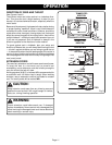
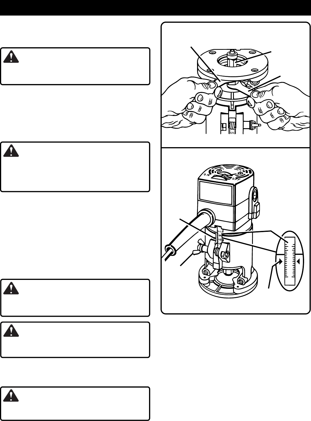
TO SET DEPTH OF CUT
See Figure 4.
1. UNPLUG YOUR TRIMMER.
WARNING:
Failure to unplug your trimmer could result in accidental
starting causing serious injury.
2. Loosen the wing bolt and move the base until the tip of
cutter touches the work surface. The depth of cut is zero
at this point.
See Figure 4.
3. Position your trimmer so that the cutter can extend
below the subbase for desired depth of cut setting.
4. Move the base to obtain the desired depth of cut. The
distance the cutter moves can be read on the depth of
cut scale. Each mark on the scale indicates a 1/16 in.
(1.6 mm) change in depth setting. Indicator points are
located on the base.
5. Securely tighten the wing bolt.
WRENCH ON
SPINDLE FLATS
WRENCH ON
COLLET NUT
CUTTER
Fig. 3
Fig. 4
0
1
3/4
1/4
1/2
DEPTH OF
CUT SCALE
INDICATOR
POINT (S)
INDICATOR
POINT (S)
WING
BOLT