


Page 18 Page 19
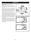
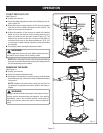
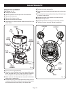
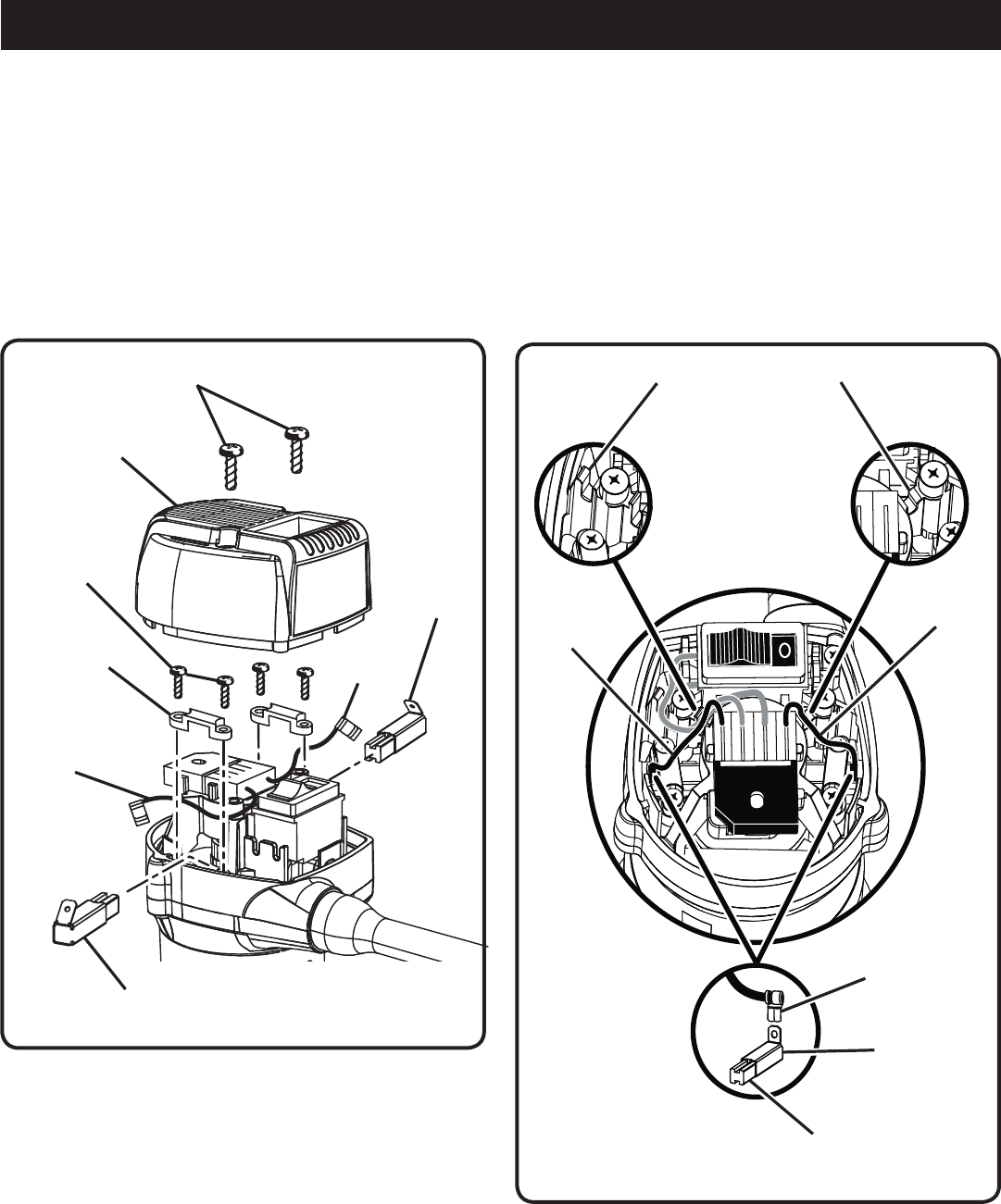
Fig. 14
SCREWS
TOP
COVER
BRUSH
ASSEMBLY
CLAMP
SCREWS
BRUSH TUBE
CLAMPS
BLACK
LEAD
RED
LEAD
BRUSH
ASSEMBLY
MAINTENANCE
BRUSH REPLACEMENT
See Figures 14 - 15.
n Unplug the trimmer.
n Remove screws from the top cover of the trimmer.
n Remove the top cover.
n Remove the clamp screws.
n Remove the brush tube clamps.
n Disconnect the red and black lead terminals from the
brush tubes.
n Remove the brush assemblies.
n Check for wear. Replace both brush assemblies when
either has less than 1/4 in. length of carbon remaining.
Do not replace one side without replacing the other.
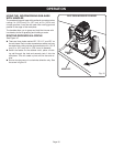
n Make sure the wire terminals are secured to the brush
tubes prior to reassembly.
n Reassemble using new brush assemblies. Make sure the
curvature of the brush matches the curvature of the motor
and that the brush moves freely in the brush tube.
n Replace the brush assemblies.
n Reconnect the red and black lead terminals to the brush
tubes.
n Ensure that the wires are placed securely in the lead traps
to prevent loose wires.
n Replace the brush tube clamps and clamp screws.
n Replace the top cover.
n Replace the screws on the top cover of the trimmer.
n Tighten all screws securely. Do not overtighten.
BLACK
LEAD
RED
LEAD
LEAD
TERMINAL
LEAD TRAP
LEAD TRAP
BRUSH
TUBE
BRUSH
Fig. 15