


30
MAINTENANCE
WARNING:
When servicing, use only identical Ryobi replacement
parts. Use of any other parts may create a hazard or
cause product damage.
WARNING:
Always wear safety goggles or safety glasses with side
shields during power tool operation or when blowing
dust. If operation is dusty, also wear a dust mask.
GENERAL MAINTENANCE
Avoid using solvents when cleaning plastic parts. Most
plastics are susceptible to damage from various types of
commercial solvents and may be damaged by their use. Use
clean cloths to remove dirt, dust, oil, grease, etc.
WARNING:
Do not at any time let brake fluids, gasoline, petroleum-
based products, penetrating oils, etc., come in contact
with plastic parts. Chemicals can damage, weaken or
destroy plastic which may result in serious personal
injury.
Electric tools used on fiberglass material, wallboard, spackling
compounds, or plaster are subject to accelerated wear and
possible premature failure because the fiberglass chips and
grindings are highly abrasive to bearings, brushes, commu-
tators, etc. Consequently, we do not recommended using this
tool for extended work on these types of materials. However,
if you do work with any of these materials, it is extremely
important to clean the tool using compressed air.
LUBRICATION
All of the bearings in this tool are lubricated with a sufficient
amount of high grade lubricant for the life of the unit under
normal operating conditions. Therefore, no further lubrica-
tion is required.
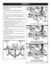
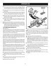
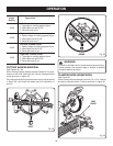
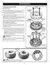
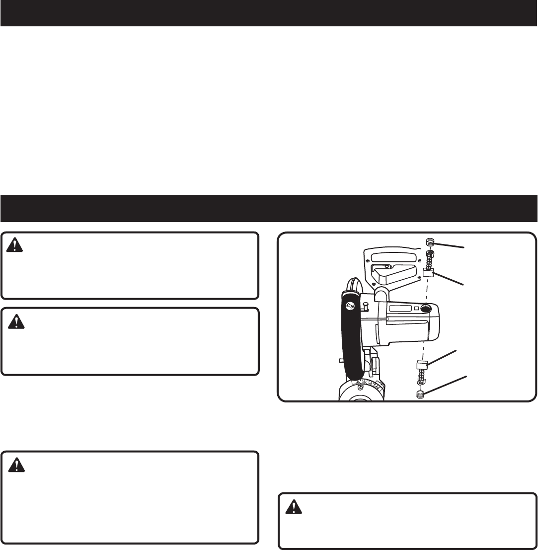
BRUSH REPLACEMENT
See Figure 43.
The saw has externally accessible brush assemblies that
should be periodically checked for wear.
Proceed as follows when replacement is required:
n Unplug the saw.
WARNING:
Failure to unplug the saw could result in accidental start-
ing causing serious injury.
n Remove brush cap with a screwdriver. Brush assembly is
spring loaded and will pop out when you remove brush
cap.
n Remove brush assembly.
n Check for wear. Replace both brushes when either has
less than 1/4 in. length of carbon remaining. Do not
replace one side without replacing the other.
n Reassemble using new brush assemblies. Make sure
curvature of brush matches curvature of motor and that
brush moves freely in brush tube.
n Make sure brush cap is oriented correctly (straight) and
replace.
n Tighten brush cap securely. Do not overtighten.
BRUSH
CAP
Fig. 43
BRUSH
CAP
BRUSH
ASSEMBLY
BRUSH
ASSEMBLY
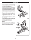
ADJUSTMENTS
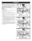
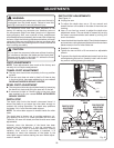
POSITIVE STOP ADJUSTMENTS
See Figure 42.
NOTE: These adjustments were made at the factory and
normally do not require readjustment.
To adjust:
n Unplug the saw.
n Using two wrenches (one on the lock nut and one for
the positive stop adjustment screw), loosen the lock nut
securing the positive stop adjustment screw.
n Loosen the bevel lock knob by turning the knob
counterclockwise.
n Square the blade to the miter table as described in the
Assembly section of this manual.
n Retighten bevel lock knob. Next, retighten lock nut
securing the positive stop adjustment screw. Recheck
blade-to-table alignment.
NOTE: The above procedure can be used to check blade
squareness of the saw blade to the miter table at both 0
°
and 45
°
angles.
The saw has two scale indicators, one on the bevel scale
and one on the miter scale. After squaring adjustments have
been made, it may be necessary to loosen the indicator
screws and reset them to zero.