


www.schneider-electric.com 2/4 S1A10942 - 02/2012
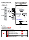
Apply power to the drive
• Ensure that Logic Inputs are not active (see Li1, Li2, Lix ).
• Apply power to the drive.
• At first power up, the drive displays nSt (3-wire control) or rdY(2 -wire control), after pushed drive displays bFr.
• On next start-ups, the drive displays nStor rdY .
Set motor parameters
• Refer to the motor nameplate for the following parameter settings.
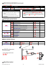
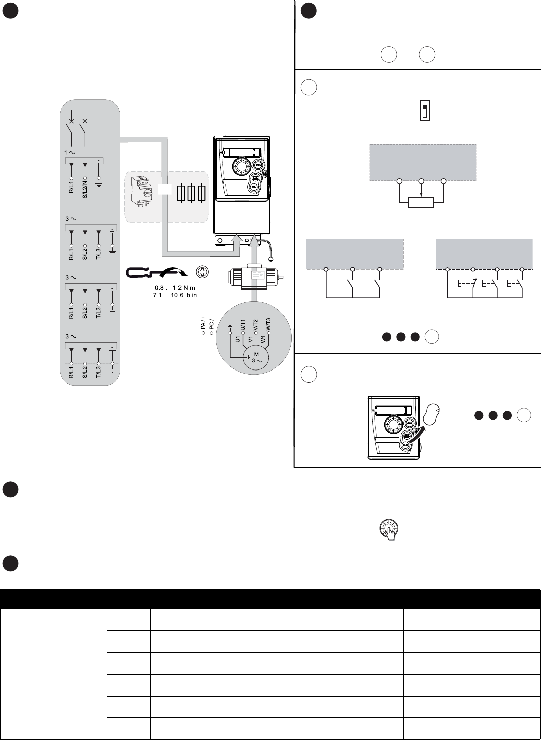
Connect power wiring
• Wire the drive to the ground.
• Check circuit breaker rating or fuse rating (see SCCR annex)
• Check that the motor voltage is compatible with the drive voltage.
Motor voltage ______Volts.
• Wire the drive to the motor.
• Wire the drive to the line supply.
Connect control wiring and
select control configuration:
or
[REMOTE configuration]
(Control by external reference)
• Ensure SW1 = ‘’SOURCE’’
• Wire the speed reference:
• Wire the command:
•Next steps, do:
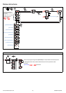
[LOCAL configuration]
(control by internal reference)
.
Menu Code Description Factory setting
Customer
setting
drC-
[MOTOR CONTROL]
bFr
[Standard mot. freq]:
Standard motor frequency (Hz)
50.0
UnS
[Rated motor volt.]:
Nominal motor voltage on motor nameplate (V)
drive rating
FrS
[Rated motor freq.]:
Nominal motor frequency on motor nameplate (Hz)
50.0
nCr
[Rated mot. current.]:
Nominal motor current on motor nameplate (A)
drive rating
nSP
[Rated motor speed]:
Nominal motor speed on motor nameplate (rpm)
drive rating
COS
[Motor 1 Cosinus Phi.]:
Nominal motor cos
ϕ on motor nameplate
drive rating
4
ATV312 M2
ATV312 M3
ATV312 N4
ATV312 S6
200/240 V
380/500 V
525/600 V
REF
RUN
CAN
ERR
MON
CONF
200/240 V
or
See
SCCR annex
5
5.1
+10 v
AI1
COM
2.2 KΩ
LI1
24 V
ATV 312
LI2
24 V
LI2
LI1
LIx
ATV 312
LI1: forward
LI2: reverse
LI1: stop
Control command 2-wire:
Control command 3-wire:
LI2: forward
LIx: reverse
OR
5.2
REF
RUN
CAN
ERR
MON
CONF
6
7
+ + +
6
8
7
9.1
Source
CLI
SINK
5.1
5.2
Do: + + +
6
87
9. 2
ENT