


3
SCHUMACHER ELECTRIC CORPORATION, 801 BUSINESS CENTER DRIVE,
MOUNT PROSPECT, ILLINOIS 60056-2179 MAKES THIS LIMITED WARRANTY
TO THE ORIGINAL PURCHASER AT RETAIL OF THIS PRODUCT. THIS LIM-
ITED WARRANTY IS NOT TRANSFERABLE.
Schumacher Electric Corporation warrants this battery charger for two years
from date of purchase at retail against defective material or workmanship. If
such should occur, the unit will be repaired or replaced at the option of the manu-
facturer. It is the obligation of the purchaser to forward the unit together with
proof of purchase, transportation and/or mailing charges prepaid to the manu-
facturer or its authorized representative.
This limited warranty is void if the product is misused, subjected to careless
handling, or repaired by anyone other than the manufacturer or its authorized
representative.
The manufacturer makes no warranty other than this limited warranty and ex-
pressly excludes any implied warranty including any warranty for consequential
damages.
LIMITED WARRANTY
THIS IS THE ONLY EXPRESS LIMITED WARRANTY AND THE MANUFAC-
TURER NEITHER ASSUMES NOR AUTHORIZES ANYONE TO ASSUME OR
MAKE ANY OTHER OBLIGATION TOWARDS THE PRODUCT OTHER THAN
THIS EXPRESS LIMITED WARRANTY. THE MANUFACTURER MAKES NO
WARRANTY OF MERCHANTABILITY OR FITNESS FOR PURPOSE OF THIS
PRODUCT AND EXPRESSLY EXCLUDES SUCH FROM THIS LIMITED WAR-
RANTY.
SOME STATES DO NOT ALLOW THE EXCLUSION OR LIMITATION OF INCI-
DENTAL OR CONSEQUENTIAL DAMAGES OR LENGTH OF IMPLIED WAR-
RANTY SO THE ABOVE LIMITATIONS OR EXCLUSIONS MAY NOT APPLY TO
YOU.
THIS WARRANTY GIVES YOU SPECIFIC LEGAL RIGHTS AND YOU MAY ALSO
HAVE OTHER RIGHTS WHICH VARY FROM STATE TO STATE.
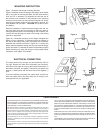
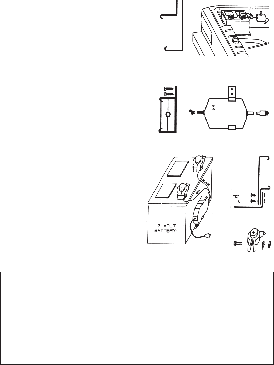
MOUNTING INSTRUCTION
Figure 1 illustrates the charger mounting brackets.
Figure 2 illustrates surface mounting of the charger to the fender
well. If using the nut and bolt provided, drill two holes between
3/16" and 1/4" in diameter. (For alignment of holes use one of
the brackets as a template.) If the backside of the mounting
surface is hard to reach, you may consider using two 1/2" sheet-
metal screws instead of nut bolt, drill a pilot hole if required, drill
holes between 1/8" and 5/32". CAUTION: Do not drill or punc-
ture battery.
Electrical installations - Route and secure supply cord and out-
put wiring away from gas line, carburetor or other hot, sharp or
moving and pinch parts to avoid damage to the insulation. Se-
cure the AC cord and plug to a cable or from using a self locking
cable tie or equivalent.
Figure No. 3 illustrates mounting of the charger alongside the
battery of your automobile. If convenient place the charger to
the side of the battery away from the engine and fan blades,
assemble the brackets as shown in figure No. 4. Loosen the
battery retaining hardware enough that you can insert the longer
portion of bracket "C" between the bottom of the battery and the
battery mounting tray. Align the charger to freely stand without
restrictions, then tighten all hardware.
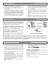
ELECTRICAL CONNECTION
The output leads of the charger are terminated with 3/8 inch
ring lugs. Remove the bolts from the battery post connector,
insert the bolt through the ring lug then place the bolt back in
the battery connector and tighten. Connect the red lead to the
positive (+) battery post and the black lead to the negative (-)
post.
If you have difficulty connecting the output leads, consult your
local auto supply store, they may assist you in finding a con-
necting device for your application.
Figure 5
Figure 3
Figure 4
Figure 1
FENDER WELL
12 VOLT
BATTERY
Figure 2