


4
Model SE-1-12S is intended for use with 12 volt battery sys-
tems only. The charger contains an electronic control circuit which
safeguards against overcharging the battery.
After reading and following the directions "
Charging battery in
vehicle" or "Charging battery out of vehicle,"
you may observe
the following conditions:
Light Color On/Off Condition
Green Off Check wall receptacle for
120 volts or check lead
connections, may be
reversed.
Green On AC Power is present.
Red On Battery charger voltage is
approximately 14 volts and
charging has stopped.
Red Off Battery voltage has
dropped one volt and the
charging has resumed.
The on/off cycle of the red light will continue, the red light will
stay on for longer periods of time as the battery becomes more
fully charged. Your charger has been designed NOT to spark if
the ring lugs on the leads accidentally touch one another, or if
the leads are connected in reverse.
The battery must measure at least 2 volts to start the charging
of the battery. The green light will be on even if the charging is
not taking place. You can verify charging by measuring the bat-
tery voltage and noting an increase in volts.
This charger is ideally suited for maintaining the battery charge
level for the following applications.
1. Storage of a battery during non-seasonal use.
2. For vehicles seldom used or placed in storage.
3. For improved battery performance during cold weather.
Smaller batteries such as those used on motorcycles and gar-
den tractors can be charged overnight.
For large automotive or marine battery which are deeply dis-
charged, it is recommended to recharge first with a larger charger
(such as a 10 amp) then use the SE-1-12S to maintain the charge
level of the battery.
If the battery is used in automobile or other application which
has its own means of charging a battery, the above time maybe
greatly reduced by partially charging the battery before apply-
ing the charger.
CHARGING BATTERY IN VEHICLE
FOLLOW THESE STEPS WHEN BATTERY IS INSTALLED IN
VEHICLE A SPARK NEAR BATTERY MAY CAUSE BATTERY
EXPLOSION. TO REDUCE RISK OF SPARK NEAR BATTERY:
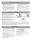
1. Position AC and DC cords to reduce risk of damage by
hood, door or moving parts.
2. Stay clear of fan blades, belts, pulleys and other parts that
can cause injury.
3. Check polarity of battery posts. POSITIVE (+) battery post
usually has a larger diameter than the NEGATIVE (-) post.
4. Determine which post of battery is grounded (connected to
the chassis). If negative post is grounded to chassis, as in
most vehicles, see item 5. If positive post is grounded to
chassis, see item 6.
5. For common negative grounded vehicle, connect positive
(red) terminal from battery charger to positive (+)
ungrounded post of the battery. Connect negative (-) ring
terminal to the vehicle chassis or engine block away from
battery as far as the leads will permit. Do not connect ring
terminal to the carburetor, fuel lines, or sheet metal body
parts. Connect to a heavy gauge metal part of the frame or
engine block or the negative post.
6. For positive grounded vehicle, connect negative (blk) ring
terminal from the battery charger to the NEG (-) ungrounded
battery post. Connect POS (+) red ring terminal to the vehicle
chassis or engine block or the POS battery post. DO NOT
connect the ring terminal to the carburetor, fuel lines, or
sheet metal body parts. Connect to a heavy gauge metal
part of the frame or engine block.
7. Only after completing steps 1 through 6, plug the extension
cord into grounded 120 volt 60 hertz outlet.
PROPER DISCONNECT PROCEDURE
1. Always unplug extension cord before doing anything else.
2. Disconnect the grounded clamp from the engine block,
framework or battery.
3. Finally disconnect the remaining clamp from battery terminal
post.
NOTE: When connected to an electrical source, the charger
may hum or buzz. This is normal. Also, the charger is
designed to get quite warm. Do not set on flammable
material.
CHARGING BATTERY OUT OF VEHICLE
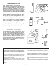
For some applications you may need to purchase a terminal
similar to that shown in figure 5 to make connections.
Check polarity of battery posts. POS (+) usually is the larger
diameter than NEG (-) post. Connect POS (+) red lead ring ter-
minal to positive post of the battery. Position yourself away from
the battery as far as possible, then connect NEG (-) blk lead
ring terminal to the negative (-) post of the battery. DO NOT
face battery when making final connection.
A marine (boat) battery must be removed and charged on
shore. To charge it on board requires equipment specially
designed for marine use.
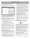
CHARGER OVERLOAD PROTECTION
Your battery charger is protected from power overload by an
automatic heat sensing switch. The protector will open with a
clicking sound and reclose after a brief cooling period.
MAINTENANCE AND CLEANING
Very little maintenance is required. As with any appliance or
tool, a few common sense rules will prolong the life of your
battery charger.
Store in a clean, dry place.
Clean case and cords with a dry or slightly damp cloth.
Figure 5
OPERATING INSTRUCTIONS