


• 4 •
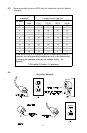
FOLLOW THESE STEPS WHEN BATTERY IS INSTALLED IN VE-6.
HICLE
A SPARK NEAR BATTERY MAY CAUSE BATTERY EXPLOSION. TO
REDUCE RISK OF A SPARK NEAR BATTERY:
Position the AC and DC cables to reduce the risk of damage by the hood, 6.1
door, or moving engine parts.
Stay clear of fan blades, belts, pulleys and other parts that can cause 6.2
injury.
Check the polarity of the battery posts. The POSITIVE (POS, P, +) battery 6.3
post usually has a larger diameter than the NEGATIVE (NEG, N, -) post.
Determine which post of the battery is grounded (connected) to the chas-6.4
sis. If the negative post is grounded to the chassis (as in most vehicles),
see step 6.5. If the positive post is grounded to the chassis, see step 6.6.
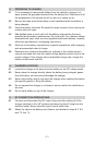
For a negative-grounded vehicle, connect the POSITIVE (RED) clip from 6.5
the battery charger to the POSITIVE (POS, P, +) ungrounded post of the
battery. Connect the NEGATIVE (BLACK) clip to the vehicle chassis or
engine block away from the battery. Do not connect the clip to the carbure-
tor, fuel lines or sheet-metal body parts. Connect to a heavy gauge metal
part of the frame or engine block.
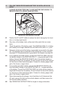
For a positive-grounded vehicle, connect the NEGATIVE (BLACK) clip 6.6
from the battery charger to the NEGATIVE (NEG, N, -) ungrounded post
of the battery. Connect the POSITIVE (RED) clip to the vehicle chassis or
engine block away from the battery. Do not connect the clip to the carbure-
tor, fuel lines or sheet-metal body parts. Connect to a heavy gauge metal
part of the frame or engine block.
When disconnecting the charger, turn all switches to off, disconnect the 6.7
AC cord, remove the clip from the vehicle chassis, and then remove the
clip from the battery terminal.
See OPERATING INSTRUCTIONS for length of charge information.6.8
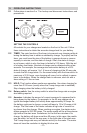
NEGATIVE GROUNDED SYSTEM