


6
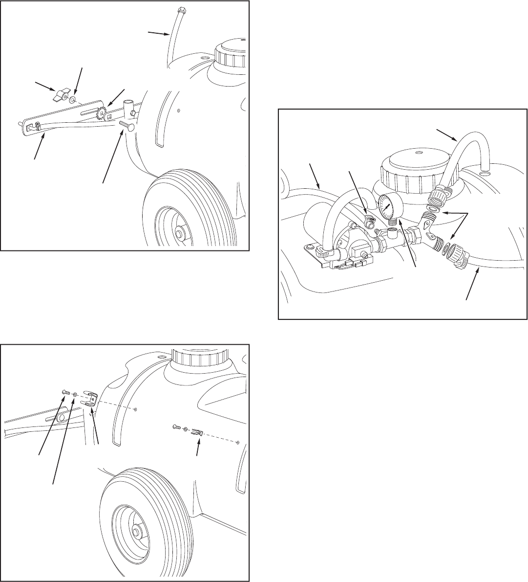
FIGURE 8
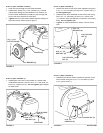
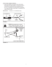
STEP 7: (SEE FIGURE 7)
• Assemble the large (P) and small (O) spray gun clips
to the side of the tank using two #10 x 1/2" screws (D)
and #10 lock washers (I).
SPRAY GUN
CLIP (P) (LARGE)
SPRAY GUN
CLIP (O) (SMALL)
#10 x 3/8"
SCREW (D)
#10 LOCK
WASHER (I)
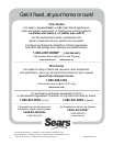
FIGURE 7
STEP 8: (SEE FIGURE 8)
• Insert a garden hose gasket (T) into the swivel nut on
the bypass/return hose. Screw the nut onto the upper
outlet of the "Y" valve fi tting. Place the other end of
the hose down through the hole at the rear of the tank.
• Insert a garden hose gasket (T) into the swivel nut on
the boom connecting hose. Screw the nut onto the
lower outlet of the "Y" valve fi tting.
• Slide the coiled hose clamp (S) onto the spray gun
hose. Push the hose onto the hose adapter on the
side of the "T" fi tting as shown in fi gure 8. Tight en the
clamp around the hose and the adapt er. Snap the
spray gun into the clips on the side of the tank.
• Carefully screw the pressure gauge (Q) into the top of
the "T" fi tting.
BOOM CONNECTING HOSE
SPRAY
GUN
HOSE
PRESSURE
GAUGE (Q)
BYPASS/RETURN HOSE
GARDEN
HOSE
GASKET (T)
COILED
HOSE
CLAMP (S)
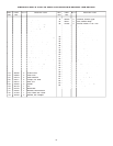
FIGURE 6
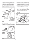
STEP 6: (SEE FIGURE 6)
• Assemble the boom bars to the boom mount brack et
using two 5/16" x 1-1/4" car riage bolts (C), tooth lock
washers (J) (be tween the bar and brack et), 5/16" fl at
washers (G) and knobs (N). The boom con nect ing
hose should extend upward.
NOTE:
Make sure the nozzles are adjusted so that the
open ings face straight down when the boom bar is in the
horizontal operating position.
CARRIAGE BOLT
5/16" x 1-1/4" (C)
KNOB (N)
5/16" FLAT
WASHER (G)
WASHER (J)
(TOOTH LOCK)
BOOM BAR
BOOM CONNECTING HOSE