


7 — ENG
D20414 Rev. 0 2/15/00
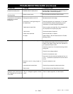
Safety Valve: If the pressure switch does not shut
off the air compressor at its cut-out pressure setting,
the safety valve will protect the tank against high
pressure by “popping out” at its factory set pressure
(slightly higher than the pressure switch cut-out
setting).
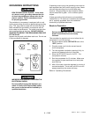
Regulator: The air pressure coming from the air tank
is controlled by the regulator. Turn the regulator knob
clockwise to increase pressure and counter-clock-
wise to decrease pressure. To avoid minor readjust-
ment after making a change in pressure setting,
always approach the desired pressure from a lower
pressure. When reducing from a higher to a lower
setting, first reduce to some pressure less than that
desired, then bring up to the desired pressure.
Depending on the air requirements of each particular
accessory, the outlet regulated air pressure may have
to be adjusted while operating the accessory.
Outlet Pressure Gauge: The outlet pressure gauge
indicates the air pressure available at the outlet side
of the regulator. This pressure is controlled by the
regulator and is always less or equal to the tank
pressure. See “Operating Procedures”.
Tank Pressure Gauge: The tank pressure gauge
indicates the reserve air pressure in the tank.
Cooling System: This compressor contains an
advanced design cooling system. At the heart of this
cooling system is an engineered fan. It is perfectly
normal for this fan to blow air through the vent holes
in large amounts. You know that the cooling system
is working when air is being expelled.
Air Compressor Pump: To compress air, the piston
moves up and down in the cylinder. On the down-
stroke, air is drawn in through the air intake valves.
The exhaust valves remain closed. On the upstroke of
the piston, air is compressed. The intake valves close
and compressed air is forced out through the exhaust
valves, through the outlet tube, through the check valve
and into the air tank. Working air is not available until
the compressor has raised the air tank pressure above
that required at the air outlet.
Check Valve: When the air compressor is operating,
the check valve is “open”, allowing compressed air to
enter the air tank. When the air compressor reaches
“cut-out” pressure, the check valve “closes”, allowing
air pressure to remain inside the air tank.
Pressure Release Valve: The pressure release valve
located on the side of the pressure switch, is designed
to automatically release compressed air from the
compressor head and the outlet tube when the air
compressor reaches “cut-out” pressure or is shut off.
If the air is not released, the motor will not be able to
start. The pressure release valve allows the motor to
restart freely. When the motor stops running, air will be
heard escaping from the valve for a few seconds. No
air should be leaking when the motor is running.
Pressure Switch: The pressure switch automatically
starts the motor when the air tank pressure drops
below the factory set “cut-in” pressure. It stops the
motor when the air tank pressure reaches the factory
set “cut-out” pressure.
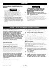
• a 3/8" open end wrench or socket to tighten handle
screws
• a 9/16" socket or open end wrench for attaching
the wheels
DESCRIPTION OF OPERATION
TOOLS NEEDED FOR ASSEMBLY