


13
EC7500.23
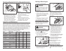
1. Turn the on-off switch On.
WARNING!
The cut-off wheel must not rotate
at idle speed. If it rotates, reduce
idle speed by adjusting the idle
adjust screw.
2. Push the decompression valve in.
3. Pull the choke all the way out and
push it back to the original position
(choke open). The throttle is
automatically set at a fast idle
position.
4. Follow Steps 5 though 12, Starting
a Cold Engine (previous page).
Starting a Warm Engine
EC7500.24
If the engine fails to start, repeat the
appropriate starting procedure for a
cold or warm engine.
WARNING!
Keep well away from fire!
If the engine still does not start,
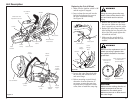
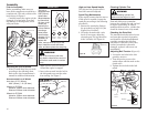
1. Pull the choke all way out.
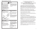
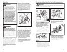
2. Unscrew the knob on the cleaner
cover and remove the cleaner
cover. See Figure 11.
If the Engine Doesn’t Start
Figure 11
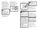
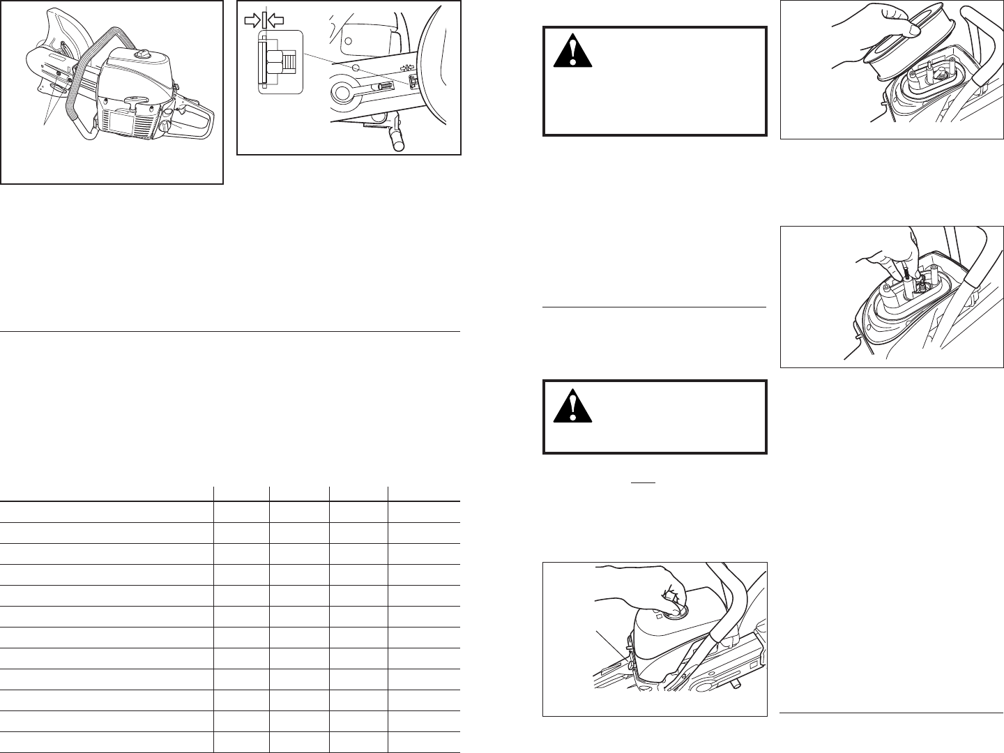
3. Unscrew the two bolts securing the
filter element, remove the filter
element. See Figure 12.
Figure 12
Choke
4. Remove the plug cap and discon-
nect the spark plug by using the
plug wrench. See Figure 13. Check
to see if the spark plug electrode is
fuel-soaked.
5. If the spark plug is wet, dry it
completely. Clear excess fuel from
the combustion chamber by
cranking the engine several times
with the spark plug is removed.
6. Reassemble the spark plug, plug
cap, filter and cleaner cover.
7. Follow the appropriate starting
procedure described above.
8. If the spark plug is dry, fuel is likely
not being supplied to the combus-
tion chamber properly.
■ Check the fuel filter and carbure-
tor. Refer to the Inspection and
Maintenance Section.
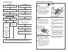
■ Refer to the Troubleshooting
Section, page 24.
If the engine still does not start,
contact your Shindaiwa dealer.
Stopping the Engine
EC7500.25
Figure 13
Let the engine run at idle speed for 2-3
minutes, then turn the on-off switch
Off.
16
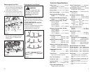
Inspection and Maintenance
Item What to Do Daily Weekly Monthly As Req’d
Air Cleaner Clean ✔
Cut-off Wheel Check & Sharpen ✔
Bolts/Screws Check & Retighten ✔
Fuel Cap Check Leakage ✔
Fuel Tank Check Leakage ✔
Wheel Guard Check Function ✔
Clutch Bearing Grease ✔
Belt Check and Adjust ✔
Spark Plug Check and Clean ✔
Cylinder Fins Clean ✔
Fuel Filter Clean ✔
Carburetor Adjust ✔
Inspection and Maintenance Requirements
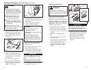
Figure 19
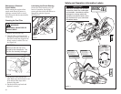
5. Making sure that the drive belt is
fully engaged in the drive pulleys,
slide the belt cover on and install
the two socket-head bolts into the
left-hand side of the mounting
surface only until the bolts bottom
on the belt cover. See Figure 19.
6mm Socket-
Head Bolts
Figure 20
6. Adjust the tension screw until the
tension indicator is in the middle of
the scale. See Figure 20.
7. Tighten the two mounting bolts
securely.
8. Reconnect the main water line,
adjust and retighten water nozzles
(if equipped with a water kit).
9. Reinstall the cutting wheel.
Reversing cutting head for flush cutting operations (cont.)
MAINTENANCE, REPLACEMENT, OR REPAIR OF EMISSION CONTROL
DEVICES AND SYSTEM MAY BE PERFORMED BY ANY REPAIR ESTABLISH-
MENT OR INDIVIDUAL. HOWEVER, WARRANTY REPAIRS MUST BE PER-
FORMED BY A DEALER OR SERVICE CENTER AUTHORIZED BY SHIN-DAIWA
KOGYO, LTD. AND USE OF PARTS THAT ARE NOT EQUIVALENT IN PERFOR-
MANCE AND DURABILITY TO AUTHORIZED PARTS MAY IMPAIR THE
EFFECTIVENESS OF THE EMISSION CONTROL SYSTEM AND MAY HAVE A
BEARING ON THE OUTCOME OF THE WARRANTY CLAIM.