


14
EC7500.27
WARNING!
■ Never permit bystanders or
animals near the unit when
starting or operating the unit.
■ Be aware of kickback!
Kickback may force the cut-off
wheel up and back toward the
operator lightning-fast. Kick-
back can occur whenever the
upper half of the cut-off wheel
touches an object. Never cut
an object using the upper-
half of the cut-off wheel.
■ When operating, always wear
snug-fitting clothing, safety
gloves, safety non-skid
footwear, hearing protection, a
dust-proof mask, a helmet and
goggles.
WARNING!
When using the cut-off saw, the
wheel guard must be securely in
position as a protection against a
broken wheel. If the wheel guard
is not in place, a broken wheel
could project fragments at high
speed and strike you or others,
possibly resulting in serious
injury.
Wet or Dry Operation
This unit is designed to be operated
for either dry or wet cutting. A water
dust-suppression kit is available for
this unit but is not supplied in the
unit packaging. Please refer to the
assembly and operating instructions
supplied with the water dust-suppres-
sion kit.
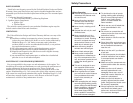
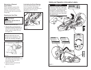
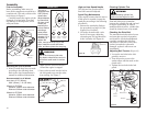
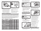
Adjusting Wheel Guard Angle
Adjust the position of the wheel guard
so that fragments will not fly toward
you if the wheel fractures. To reposi-
tion the wheel guard, loosen the lock
knob (counterclockwise). When the
wheel guard is positioned correctly,
securely tighten the lock knob.
See Figure 14.
Operation
Figure 14
Cutting
This unit performs most efficiently
when cutting between 8,500 and 9,500
min
-1
(rpm). While running the engine
at full throttle, apply slight pressure to
the cut-off wheel against an object so
that engine speed stays at 8,500–9,500
min
-1
(rpm). Too much pressure to the
wheel will lower wheel speed, reduc-
ing cutting efficiency considerably.
1. Make sure you have a clear work
area and secure footing.
2. Position the cut-off wheel vertically
to an object. Start cutting at a low
speed and then gradually acceler-
ate the speed.
Wheel
Guard
Lock
Knob
Wheel Guard
Locked
Wheel Guard
Free
15
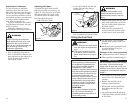
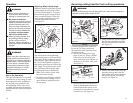
NOTE:
For units equipped with a water kit,
loosen the (2) water nozzles and
disconnect the main water line from
the double nozzle.
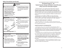
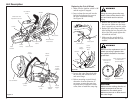
1. Remove the cutting wheel (See
pages 10 and 11). Using a Phillips
screwdriver, loosen the tension
screw until the tension indicator is
all the way to the front of the scale.
See Figure 15.
Figure 15
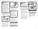
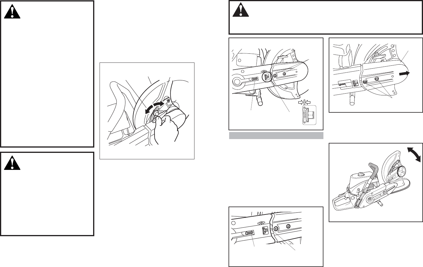
Figure 18
4. Remove the blade mount from the
mounting surface and rotate the
blade mount 180
0
, then remount to
the right hand side of mounting
surface. See Figure 18.
Reversing cutting head for flush cutting operations
Tension Screw
Tension
Indicator
Belt Guard
WARNING!
Before performing any work on the cut-off saw, make sure the engine is
stopped and the ignition switch is OFF.
Remove Cutting Wheel
Loosen
Two Bolts
2. Back off tension screw another 4-5
turns so that adequate clearance is
achieved where the tension screw
contacts the mount when the mount
is turned over. See Figure 16.
Figure 16
Mount
Tension Screw
Figure 17
3. Using a 6mm hex wrench, remove
the two belt guard bolts and slide
the belt guard forward to remove.
See Figure 17.
6mm Socket-
Head Bolts