


Foreseen
Use
Of
The
Tool
-
5062
This die grinder is primarily designed for use with
bonded
abrasive mounted point grinding wheels. It may also be used with steel rotary
files and carbide
buns
provided their speed rating matches the speed of the grinder.
This tool should not be fitted with cut off wheels, saw blades, drill bits, etc. If there Is any doubt about the correct use of this product
contact your supplier for advice.
Also make sure that the shank size of the attachment to be driven matches with the collet size fined in the grinder and that the maximum
allowed running speed of the attachment exceeds that marked on the grinder.
There are special rulesgoverning the use of bonded abrasive mounted point grinding wheels
-
for details see section "Operating."
Work
Stations
The tool should only be used as a handheld, hand operated tool. It is always recommended that the tool is used when standing on a solid
floor. It can be used in other positions, but before any such use, the operator must be in a secure position having a firm grip and footing
and be aware of the extra safety precautions that must be observed when using grinding machines.
Putting Into Service
Air
Supply
Use a clean lubricated air supply that will give a measured air pressure at the tool of 90 PSiG (6.2 bar) when the tool is running with the
trigger~lever fully depressed. Use recommended hose size and length. It is recommended that the tool Is connected to the air supply as
shown In figure 1. Do not connect the tool to the air line system without Incorporating an easy to reach and operate air shut off valve.The
air supply should be lubricated. It is strongly recommended that an air filter, regulator, lubricator
(FRL)
Is used as shown in Figure
1
as
this will supply clean, lubricated air at the correct pressure to the tool. Details of such equipment can be obtained from your supplier.
If
such equipment Is not used, then the tool should be lubricated by shutting off the air supply to the tool, depressurizing the line by pressing
the trigger on the tool. Disconnect the air line and pour into the hose adaptor a teaspoonful (5ml) of a suitable pneumatic motor lubricating
oil preferably incorporating a rust inhibitor. Reconnect tool to air supply and run tool slowly for a few seconds to allow air to circulate the
oil. If tool is used frequently, lubricate on daily basis and if tool starts to slow or lose power.
It is recommended that the air pressure at the tool while the tool is running is 90 PSU6.2 bar.
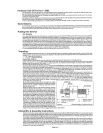
Using a screwdriver, turn the valve (8) untilthe slot aligns with the
center
line
of the tool tor maxlmum speed gnd power and roiate
1
Figure
2'
Gripping length
of
collet
and
chuck
Operating
Select a suitable mounted point that
has
a free running speed higher than the maximum running speed marked on the tool. Make sure
that the diameter of the shank exactly matches the diameter of the collet mounted In the grinder.There are two standard sizes of collet
available for use with this grinder, i.e.,
1.
-
114" Dia.(0.250 ins)
(6.35
mm)
2.
-
6mm Dia. (0.236 ins)
Always match correctly the shank size to the collet size. If uncertain, have parts measured by a competent person.
Push the shank
as
far
as possible into the coliet and tighten the collet nut using the spanners provided on the collet nut and the output
spindle. The shank of the mounted point may be pulled toward from the maximum insertion length, but always ensure a maximum
gripping length of not less than 10mm
-
see Figure 2.
Be aware that the allowed running speed of the mounted point is lowered because of an Increase In the iengthof the shank between the
end of the collet and the body of the mounted point.This distance is shown inFigure 2.asULo'and is called the overhang. The information
with respect to mounted polnt, permissible running speed and reduction in running speed due to an increase in overhang is available
from the supplier of the mounted points. It the Increase in overhang for access reasons takes the permissible running speed of the
mounted point below the free running speed of the grinder, select
a
smaller diameter mounted point.
The fitting of the mounted point should be done by
a
trained operator. When first starting the grinder with a new point or wheel fitted, the
grinder should not be near other persons and be held in
a
protected area. 1.e. under
a
bench, and run fora few seconds.This will protect
personnel from possible effects of damage to the mounted polnt or wheel before it is was fitted to the grinder i.e. wheel breakage.
Always use
eye
protection and wear protective gloves
If
there are sharp edges in the work area. The tool and the grinding process can
create
a
noise level such that the use of ear protectors is advised. If the grinding process creates
a
dust, then use a suitable breathing
mask. Check that the material being worked will not cause harmful dust or fumes. If this is so, then special breathing masks may be
required. If the grinder vibrates when first fitting
a
mounted point or during operation, remove from service immediately and
90'
for minimum speed and power. An air strainer is located in the
adaptor bushing (14) of the grinder. Remove adaptor bushing
(14)
to clean strainer.
correct fault before continuing to use.
Do not apply excessive pressure as this will reduce the cutting
efficiency and can bend the shank of the mounted point causing
vibration and the possibility of breakage. Apply light loads to
allow the wheel to cut.
Handle the grinder with care. If the grinder is dropped, carefully
check the mounted polnt for damage, 1.0. cracks, chipping,
and
start for the first time as for fitting a new wheel, i.e. under a bench.
Never exceed the maximum air pressure. If there is this possibii-
ity, always use this grinder with
a
pressure reducing
valve
fitted
in the supply line.Your supplier will advise of suitable equipment.
This grinder Is lilted with
a
speed regulator and the speed may
be reduced by rotating alr regulator (8) with a suitable screw-
driver. When making speed checks, always rotate the air
regulator to the position that gives the highest maximum speed.
The lever on a die grinder is the ontoff valve,Thg air flow
can
be
controlled by the adiustino of the valve
(81
ODDOS~~~
the lever.
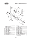
Dismantling
&
Assembly
Instructions
Disconnect tool from airsupply. Grip chuck spindle (27) with wrench
(30)
and collet nut (29) with wrench
(30)
and unscrew collet nut (29)
and take out mounted point grinding wheel as fitted. Remove collet nut
(29)
and pull out collet (28). Grip motor housing
(1)
by the flats at
the rear end In a vise fitted with soft jaws and drive out pin (13) and take off safety throttle lever (12). Unscrew hose adaptorwith screen
(14)
and
take
off O-ring (15) and muffler (37) from hose adaptor
(14).
Unscrew cap housing (26). Unscrew clamp nut
(25)
and grip chuck spindle (27) and pull out spindle (27) with motor assembly attached.
Grip or support rear end plate (17) and tap the rear end of rotor (18) to drive it through rear end plate (17) and bearing (16). With a
suitable punch lap out bearing
(16)
from rear of end plate (17).Take off cylinder (21) noting
US
orientation to other parts for reassembly.
Remove
4
rotor blades
(19)
from rotor
(18).
Grip mtor (18) being
very
careful not to damage or raise burrs on it and unscrew chuck
spindle (27) from mtor (18) to release spindle collar (23) and fmnf end plate
(22)
with bearing (24) assembly. With a suitable punch tap
out bearing (24) from front end plate (22).
Collet
Holder
D
=
diarderof ~'~~ounted point
S
=
diameter of shank
T
=
length of mounted point Lg
=
gripping length
Lo
=
overhand
Page
No
2