


2
E. Butt connect the battery cable wires to the red and red/black wires on the power cable. Route
cable to the battery and connect to the positive (+) terminal, or an auxiliary terminal block as
provided some vehicles.
F. WHITE WIRE (Ignition Sense) is routed to the fuse block or other ignition source. This wire
must see +12 volts when the key is turned on or the SFGH-100 will not operate.
CAUTION: The battery cable connector and ignition sense lead are both fused for the SFGH-100’s
protection. The battery cable fuses are 20 amp. and the ignition sense uses a 3 amp. fuse. Both are
standard ATO type. NEVER REPLACE A FUSE WITH ANYTHING BUT THE PROPER SIZE. SERIOUS
DAMAGE COULD RESULT.
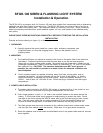
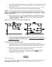
G. Refer to figures 2 & 3 below. The SFGH-100 flasher splices into the headlight circuit at a
single point, and this point is after the headlight wire harness split between the Headlights.
The BLUE & ORANGE wires in the flasher harness may be installed in either leg of the
headlight wiring as shown.
Figures 2 & 3 Location of Slice into Hi-Beam Headlight Wiring:
H. Alternating lights such as grille lights or deck lights (Caution: 8 amps. maximum ) may be
connected to the BLACK and YELLOW wires from the flasher harness.. Use silicone filled butt
connectors and be sure to make solid connections. If Not Used the Yellow and Black wire
MUST NOT touch ground.
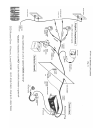
4. CONTROL HEAD & CABLE INSTALLATION
A. Find a location from which the SFGH-100 Control Head can easily be operated, and
concealed if necessary. If the Control Head mounting bracket is used, mount it to the Control
Head using the 6-32 x 3/8” thread cutting screws provided. Carefully mount the bracket.
B. Route the 12-pin plug (P1) under the carpet to the trunk, and plug it into the Amplifier/
Flasher unit P1 connector. Be sure to strain relieve the cable.
C. If radio rebroadcast is desired, connect the 22ga. zip cord provided across the speaker
terminals of the radio to be monitored. The rebroadcast feature can be disabled by
unplugging the in-line 2-pin connector.
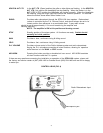
OPERATION
Refer to figure 4 below.
All functions of the SFGH-100, except on & off, are controlled from a small Control Head. The vehicles
key will turn the unit on & off. The SFGH-100 draws no current unless a function is activated.
Control Head functions are as follows: