


-12-
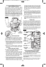
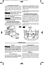
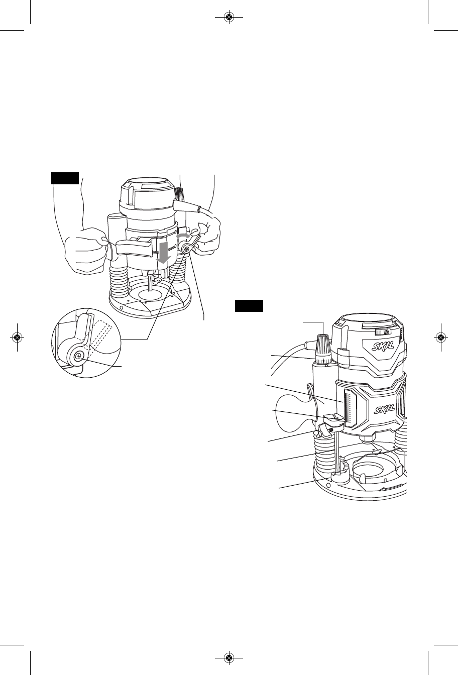
DEPTH ADJUSTMENT WITH PLUNGE
BASE PLUNGING ACTION
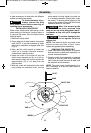
The plunge feature simplifies depth
adjustments and will allow the cutting bit to
easily and accurately enter the workpiece. To
lower, loosen plunge lock lever (Fig. 11), and
apply downward pressure until you reach
desired depth, then tighten plunge lock lever.
Loosen lever and release pressure and the
router will automatically retract the bit from the
workpiece. It is advisable to retract the bit
whenever it is not engaged in work piece.
ADJUSTING THE PLUNGE LOCK LEVER
You can adjust or reposition the plunge lock
lever for comfort, or to compensate for wear.
1. With the plunge lock lever in the locked
position (upright position), remove (counter
clockwise) the retaining screw located in the
middle of the lever.
2. Move lever to desired location, replace the
restraining screw and washer and tighten
(clockwise).
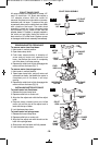
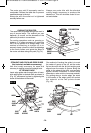
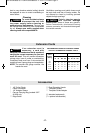
DEPTH ROD AND TURRET
The depth rod and depth stop turret are used
to control cutting depth as follows:
1. With the bit installed, gently lower the motor
until the tip of the router bit just contacts the
level surface the router is sitting on. This is
the “zero” position, from which further depth
adjustments can be accurately made.
2. To set a desired depth of cut, rotate the
depth stop turret until the lowest step is
aligned with the depth rod. Loosen the depth
indicator knob and lower the depth rod unit it
contacts the lowest step of the turret. Slide
the depth indicator until the line indicator
points to zero on the depth scale, indicating
the point at which the bit just contacts the
work (Fig. 12).
3. To set a desired cutting depth, slide the
depth rod up until the depth indicator point
attains the desired cutting depth, and secure
the rod in position by firmly tightening the
depth indicator knob.
4. The desired depth of cut may now be
achieved by plunging the router until the
depth rod contacts the selected stop on the
turret.
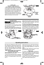
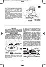
DEEP CUTS
For deeper cuts, make several progressively
deeper cuts by starting with the highest step on
the depth turret, and after each cut, rotate the
depth turret to progressively lower steps as
desired, until the final depth (lowest step or flat)
is reached. Steps progress by 1/8" increments.
To be certain that your depth settings are as
desired, you may want to make test cuts in
scrap material before beginning work.
DEPTH ADJUSTMENT WITH PLUNGE
BASE FINE ADJUSTMENT KNOB
The fine depth adjustment knob allows precise
bit height adjustments on your router.
To use the fine adjustment feature, turn the
knob clockwise to lower, or counterclockwise
to raise the bit.
(Note that one full turn of the knob will raise or
lower the bit approximately 1/16" of an inch.)
FIG. 11
1
1
/
2
1
1
/
2
0
DEPTH STOP
TURRET
DEPTH
SCALE
KNOB
FIG. 12
PLUNGE
LOCK LEVER
DEPTH ROD
DEPTH
INDICATOR
FINE ADJUSTMENT
KNOB
INDICATOR
RING
RESTRAINING SCREW
SM 1619X04663 05-11:SM 1619X04663 05-11 5/3/11 8:14 AM Page 12