


VARIABLE SPEED CONTROLLED
TRIGGER SWITCH
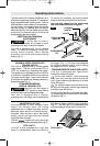
Your tool is equipped with a variable speed
trigger switch. The tool can be turned "ON" or
"OFF" by squeezing or releasing the trigger.
The speed can be adjusted from the minimum
to maximum nameplate RPM by the pressure
you apply to the trigger. Apply more pressure
to increase the speed and release pressure to
decrease speed (Fig. 1).
FORWARD/REVERSING
LEVER & TRIGGER LOCK
After tool use, lock trigger in
“OFF” position to help prevent
accidental starts and accidental discharge.
Your tool is equipped with a forward/
reversing lever and trigger lock located above
the trigger (Fig. 1). This lever was designed
for changing rotation of the bit, and for locking
the trigger in an “OFF” position.
FORWARD/REVERSE INDICATOR LIGHTS
Your tool is equipped with lights which
indicate the rotation of the bit.
For forward rotation, (with bit pointed
away from you) move the lever to the far left
and a green indicator light depicting a forward
arrow will light up.
For reverse rotation move the lever to the
far right and the green indicator light depicting
a reverse arrow will light up.
To stop in either direction just release the trigger.
To activate trigger lock move lever to the center
off position (Fig. 1).
The Skil model 2410 Cordless Drill/Driver has a
collet that accepts only standard 1/4” hexagonal
shank accessories with power groove. The low
RPM capability of this model is not a deficiency.
O
n the contrary, low speed means high torque
and high torque is a definite plus for efficient
drilling and driving. The low speed also provides
more control to prevent stripout of the screw
and damage to the work surface.
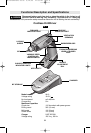
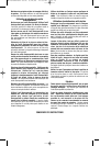
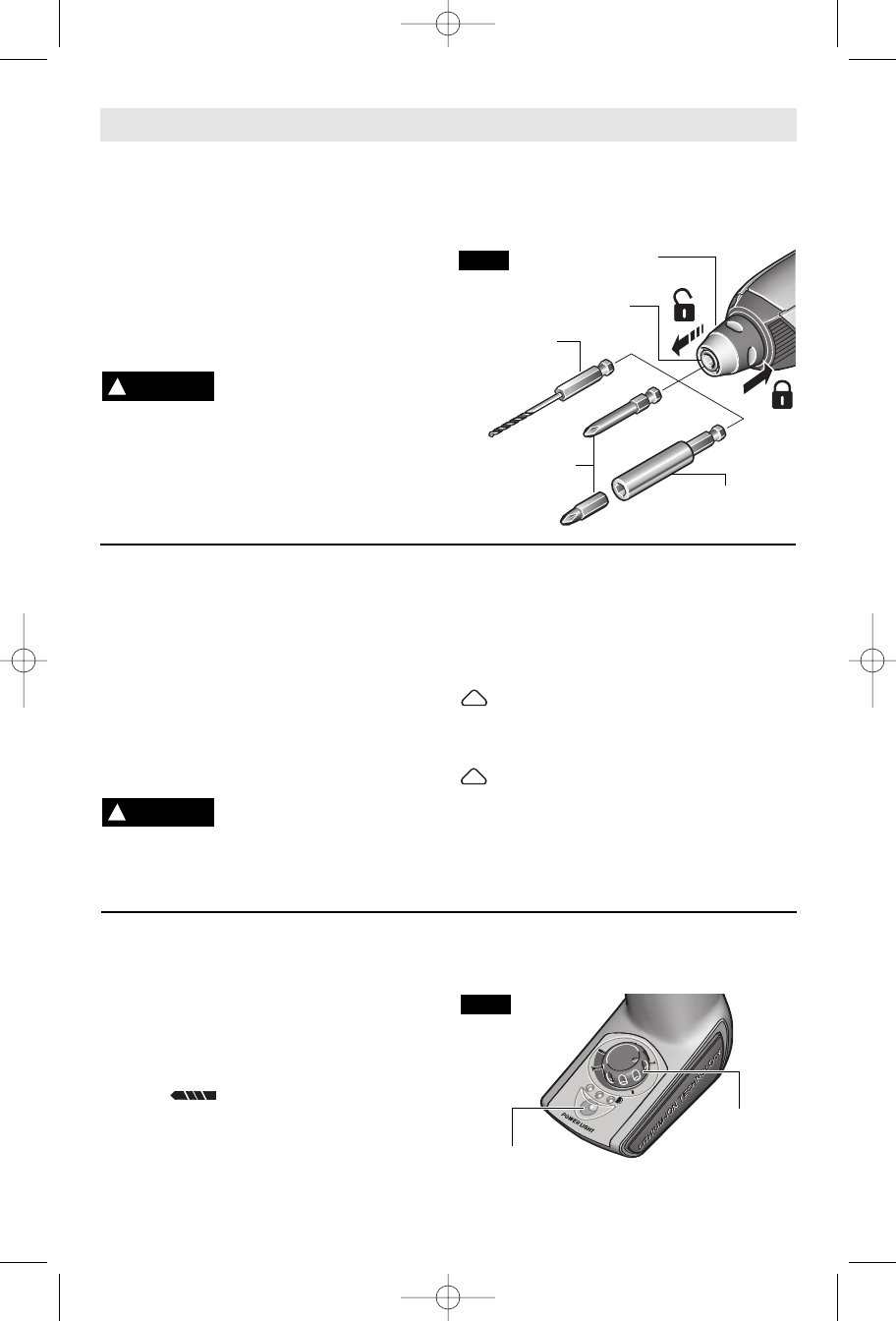
INSERTING AND REMOVING
ACCESSORIES
To avoid loss of control,
ensure bit is locked in chuck
by pulling on bit after it has been inserted.
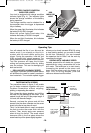
Your tool is equipped with a quick release
chuck. To insert an accessory, simply pull
locking sleeve forward, insert desired
accessory into chuck and release locking
sleeve (Fig. 2).
To remove an accessory, pull locking sleeve
forward and simply remove it from the chuck.
O
ne inch bits should only be used along
w
ith a bit holder as shown in figure 2.
-9-
Operating Instructions
!
WARNING
CHUCK
FIG. 2
SCREWDRIVER
BIT
BIT
HOLDER
LOCKING
SLEEVE
HEX-SHANK
DRILL BIT
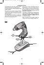
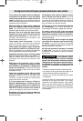
ADJUSTABLE CLUTCH
Your tool features 10 clutch settings. Output
torque will increase when the torque
adjustment dial is rotated clockwise, and will
decrease when the dial is rotated counter-
clockwise. When the dial is set to the correct
setting, the tool will stop when the desired
torque has been reached.
The Drill “ ” position will lock up the clutch
to permit drilling and driving heavyduty work (Fig. 3).
SITE-LIGHT™
Your tool is also equipped with a light that
turns on automatically when the switch is
activated for better visibility during operation
(Fig. 3). The Site-Light™ is maintenance free
and was designed to last the life of your tool.
TORQUE
ADJUSTMENT
DIAL
SITE-LIGHT™
FIG. 3
!
WARNING
BM 1619X01525 06-06 6/14/06 11:30 AM Page 9