


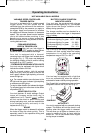
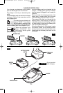
Release battery pack from tool by pressing the
battery release button and sliding pack out of
handle base (Fig. 6). To insert battery, align
battery and slide battery pack into tool until it
locks into position. Do not force.
1. The charger was designed to fast charge
the battery only when the battery temperature
is between 32˚F (0˚C) and 113˚F (45˚C). If the
battery pack is too hot or too cold, the charger
will not fast charge the battery. (This may
happen if the battery pack is hot from heavy
use). When the battery temperature returns to
between 32˚F (0˚C) and 113˚F (45˚C), the
charger will automatically begin charging.
2. A substantial drop in operating time per
charge may mean that the battery pack is
nearing the end of its life and should be
replaced.
3. Remember to unplug charger during storage
period.
4. If battery does not charge properly:
a. Check for voltage at outlet by plugging in
some other electrical device.
b. Check to see if outlet is connected to a
light switch which turns power “off” when
lights are turned off.
c. Check battery pack terminals for dirt.
Clean with cotton swab and alcohol if
necessary.
d. If you still do not get proper charging,
take or send tool, battery pack and
charger to your local Skil Service Center.
See “Tools, Electric” in the Yellow Pages
for names and addresses.
Note: Use of chargers or battery packs not
sold by Skil will void the warranty.
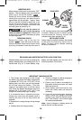
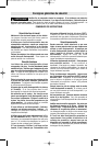
INSERTING BITS
M
ove reverse switch lever to the center “OFF”
p
osition. Remove battery pack and rotate the
clutch ring to the drill bit symbol “ ”.
Rotate the chuck sleeve counter-clockwise
viewing from chuck end, and open chuck to
approximate drill bit diameter. Insert a clean
bit up to the drill bit flutes for small bits, or as
far as it will go for large bits. Close chuck by
rotating the chuck sleeve clockwise and
securely tighten by hand (Fig. 4).
Do not use the power of
the drill while grasping
chuck to loosen or tighten bit.
Friction burn
or hand injury is possible if attempting to grasp
the spinning chuck.
REMOVING CHUCK
Rotate the clutch ring to the drill bit
symbol “ ”. Open the chuck all the way,
remove left-hand thread screw inside chuck
by turning it clockwise. Insert the short arm of
a 3/8" hex key wrench and close jaws on flats
of wrench. Strike long arm of wrench sharply
counterclockwise, remove wrench and
unthread chuck from spindle (Fig. 4).
INSTALLING CHUCK
Always keep the spindle threads, the threads
of the chuck and securing screw free of
debris. To install a chuck, reverse “removing
the chuck” procedure.
-10-
!
WARNING
IMPORTANT CHARGING NOTES
RELEASING AND INSERTING BATTERY PACK FROM TOOL
FIG. 4
CLOCKWISE
CHUCK SLEEVE
COUNTER
CLOCKWISE
SM 1619X01949 06-07 6/29/07 12:20 PM Page 10