


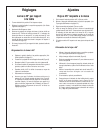

40
Adjustments
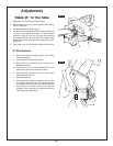
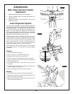
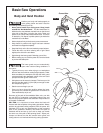
Miter Scale (Vernier) Indicator
Adjustment
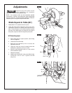
1. Raise the head assembly to the full-up position.
2. Loosen the Phillips screw
1 that holds the indicator 2 in
place (Figure 12).
3. Position the indicator
2 to align with the 0° miter mark 3.
Tighten the screw
1.
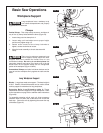
Laser Alignment System
Your miter saw is equipped with a laser alignment system that
uses two parallel laser lines to identify the material that will be
removed by the blade. The two laser lines are set to the kerf
of the blade supplied and indicate the outer edges of the
blade. If you use a blade with a different kerf, the laser lines
will need to be adjusted to match the kerf of the new blade.
You should adjust the laser lines to whichever side of the
blade the user would prefer the cut line to be on.
The tool power cord must be plugged in but you do not have to
activate the trigger to use the laser. The laser alignment system can
be turned on or off by using the switch
24 shown on page 8. When
the laser switch is turned on, the laser will automatically activate
when you approach the tool. The laser will continue to stay on as
long as you are in front of the tool. The laser will automatically turn
off after about 8 seconds when you are away from the tool.
Before using the tool, make sure that the laser line is properly aligned
(see Adjustments Section). The laser beam can become misaligned
by vibrations.
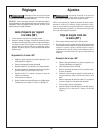
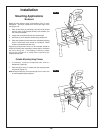
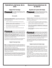
Checking
1. Set the bevel and miter to 0 degrees.
2. Clamp a scrap piece of wood onto the cutting surface.
3. Plug power cord into power source to power laser.
4.
Perform a cut into the wood without cutting all the way through.
5. Lock out the trigger so that the motor cannot be energized (See
Switch Activation section).
6. Turn the laser power switch on and stand in front of the tool to
activate laser.
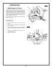
7. The space between the two laser beams
4 should be centered over
the entire length of the cut (Figure 13).
8. Continue to the adjusting section if the laser is not aligned.
Adjusting
1.
Use a small flat head screwdriver to adjust the laser alignment.
2. Rotate the back adjustment screw
5 to adjust the parallelism of the
laser lines to the cut in the work piece.
3.
Rotate the front adjustment screw
6 to center the laser lines over
the cut in the work piece (Figure. 14).
FIG. 12
5
6
0º
1
2
3
4
4
FIG. 13
FIG. 14