


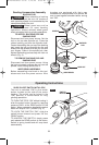

SLIDE ON-OFF SWITCH WITH LOCK
The tool is switched “ON” by the switch
button located at the side of the motor
housing. The switch can be locked in the
“ON” position, a convenience for long
grinding operations.
TO TURN THE TOOL “ON” without locking it,
slide the switch button forward by applying
pressure ONLY at the REAR portion of the
button. When pressure is released the switch
button will snap to “OFF” position (Fig. 5).
TO LOCK THE SWITCH “ON”, slide the
switch button forward and press “IN” the
FRONT portion.
TO UNLOCK THE SWITCH, simply press
and release the REAR portion of the button.
Switch is spring loaded and will snap back
automatically.
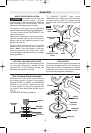
Sanding Accessories Assembly
BACKING PAD
Before attaching a backing
pad be sure its maximum
s
afe operating speed is not exceeded by the
nameplate speed of the tool.
Wheel guard may not be
used for most sanding
operations. Always reinstall wheel guard
when converting back to grinding operations.
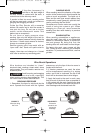
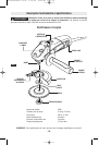
TO INSTALL BACKING PAD AND
SANDING DISC
Disconnect tool from power source. Set the
tool on its top side (spindle up). Place the
rubber backing pad onto the spindle shaft.
Center the sanding disc on top of the backing
pad. Insert the lock nut through the disc and
thread onto the spindle as far as you can with
your fingers. Press in the spindle lock, then
tighten the backing pad securely with lock nut
wrench (Fig. 4).
TO REMOVE BACKING PAD AND
SANDING DISC
Disconnect tool from power source. Using
the lock nut wrench unscrew the nut from the
spindle, while holding spindle lock in.
WIRE BRUSH ASSEMBLY
Before assembling wire brush to this tool,
disconnect from the power source. Wire
brushes are equipped with their own
threaded hub, simply thread on to spindle. Be
sure to seat against shoulder before turning
tool “ON”.
!
WARNING
!
WARNING
Operating Instructions
-8-
SWITCH
BUTTON
SANDING
DISC
BACKING
PAD
LOCK NUT
WIRE BRUSH
SPINDLE
FIG. 4
FIG. 5
SM 2610938703 03-06 3/15/06 8:08 AM Page 8