


Use wheel guard with disc
grinding wheels. Always
close the latch to secure the guard. Keep the
guard between you and the wheel. Do not
direct guard opening toward your body.
The position of the guard can be adjusted to
accommodate the operation being performed.
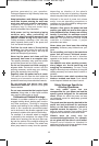
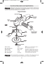
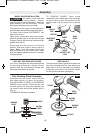
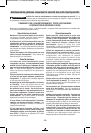
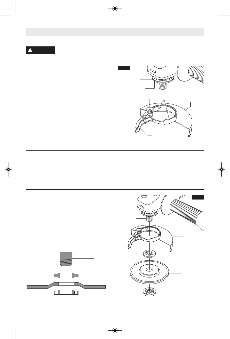
To attach wheel guard DISCONNECT tool
from power source.
Open guard release/lock latch and position
guard on spindle neck so that the three bumps
on guard, line up with the three notches on the
spindle neck (Fig. 2).
Rotate guard either direction to desired
position, and close latch to secure guard in
place. 16' If lock latch does not securely
clamp the guard to the spindle neck, open
latch and tighten adjustment screw to increase
clamping tension.
TO REMOVE GUARD: Open guard
release/lock latch, rotate guard until the bump
on guard lines up with the notches on the
spindle neck, and lift guard off the spindle
neck.
55'/$.;
-9-
Your tool is equipped with a threaded spindle
for mounting ac ces sories. Always use the
supplied lock nut (and backing flange) that
has same thread size as spindle.
The side handle used to guide and balance the
tool can be thread ed into the front housing on
either side of the tool, depending on per sonal
preference and comfort. Use the side handle
for safe control and ease of operation.
!
WARNING
+5%4+0&+0)*''.55'/$.;
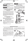
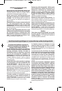
Disconnect tool from power source. Be sure
that wheel guard is in place for grinding.
Place BACKING FLANGE and GRINDING
WHEEL on the spindle. Thread on the lock
nut and tighten nut using the supplied lock
nut wrench, while holding the spindle lock in
(Fig. 3).
TO REMOVE: Reverse procedure.
GRINDING
WHEEL
LOCK NUT
SPINDLE
WHEEL
GUARD
BACKING
FLANGE
LOCK NUT
GRINDING
WHEEL
BACKING
FLANGE
SPINDLE
GUARD
RELEASE / LOCK
LATCH
SPINDLE
NECK
BUMPS
ADJUSTMENT
SCREW
NOTCHES
WHEEL
GUARD
FIG. 2
FIG. 3
SM 2610008537 11-09:SM 2610008537 11-09 11/12/09 8:33 AM Page 9