


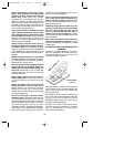
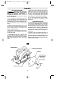
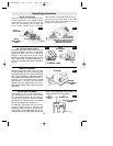
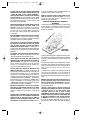
DEPTH ADJUSTMENT
Disconnect plug from power source. Loosen
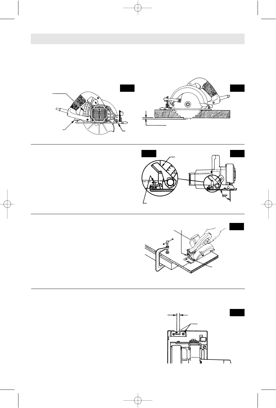
the depth adjustment lever located between
the guard and handle of saw. Hold the foot
down with one hand and raise or lower saw
by the handle. Tighten lever at the depth
setting desired. Check desired depth (Fig. 3).
Not more than one tooth length of the blade
should extend below the material to be cut,
for minimum splintering (Fig. 4).
-9-
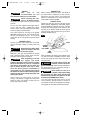
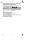
90° CUTTING ANGLE CHECK
Disconnect plug from power source. Set foot
to maximum depth of cut setting. Loosen bevel
adjustment lever, set to 0° on quadrant,
retighten lever and check for 90° angle
between the blade and bottom plane of foot
with a square (Fig. 6). Make adjustments by
turning the small alignment screw, if necessary
(Fig. 5).
BEVEL ADJUSTMENT
Disconnect plug from power source. The foot
can be adjusted up to 45° by loosening the
bevel adjustment lever at the front of the saw.
Align to desired angle on calibrated quadrant.
Then tighten bevel adjustment lever (Fig. 7).
Because of the increased amount of blade
engagement in the work and decreased
stability of the foot, blade binding may occur.
Keep the saw steady and the foot firmly on the
workpiece.
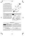
Operating Instructions
ADJUSTABLE LINE GUIDE
For a straight 90° cut you can use the left or
right side of notch in the foot. For 45° bevel
cuts, use the right side (Fig 8). The guide can
be adjusted to allow for variation in blade
thicknesses for whichever side of the blade
the user would prefer to cut the line on.
TO ADJUST: Disconnect plug from power
source. Loosen but don’t remove, the
adjustment screws enough so the guide can
move freely. Set a straightedge flat on the
preferred side of the blade, lining up both the
edge of the straightedge and the edge of the
guide where the 0° mark is located.
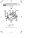
FOOT
DEPTH
ADJUSTMENT
LEVER
DEPTH
QUADRANT
FIG. 3
FIG. 4
ONE TOOTH LENGTH SHOULD
PENETRATE WOOD FOR
MINIMUM SPLINTERING
BEVEL
ADJUSTMENT
LEVER
ALIGNMENT SCREW
FIG. 6
FIG. 5
QUADRANT
BEVEL
ADJUSTMENT
LEVER
FIG. 7
90°
VERTICAL
CUTS
45°
BEVEL CUTS
GUIDE ADJUSTMENT
SCREWS
FIG. 8
SM 2610905556 1/03 1/9/03 11:24 AM Page 9