


Cart Assembly
NOTE: Sort out the hardware and arrange by size and
type. Refer to figure 1.
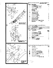
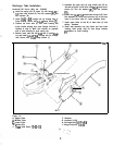
1. Install the wheel assemblies (A, figure 2) to the
frame (B). Place the head of the
swivel
wheel on the
end of the frame. Align the holes and place four
3/8-
16 x 1 hex bolts up through the frame and head of
the swivel. Secure with four flat washers (13/32 I.D.,
7/8 O.D.) and 3/S-16 locknuts.
Figure 2
A. Wheel Assembly
6. Frame
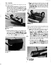
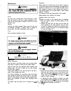
2. Install the U-bracket (A, figure 3) to the bottom of the
box (B). Place the three
5/16-20
x
3/4
slotted truss
head bolts and three flat washers (1 l/32 I.D., 3/4
O.D.) through the inside of the box and the U-brack-
et. Secure with three
5/16
lo&washers and nuts.
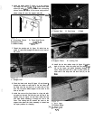
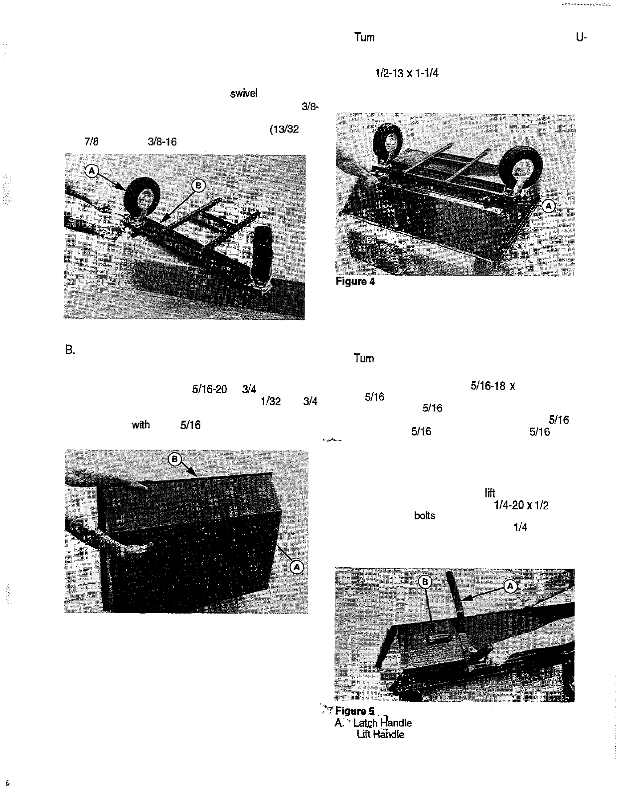
NOTE: The latch handle (A, figure 5) is located on the
right hand side on cart, Mfg. No. 169 1526 and on the left
hand side on cart, Mfg. No. 1692085.
4. Turn box with frame upright and install the latch han-
dle (A, figure 5) and two lii handles (B) as follows:
a. Latch Handle: Place one 5116-18 x 1 hex bolt with
5/16 spring washer through the inside of the box.
Next place a
5116
flat washer over the bolt on the
outside of the box, the latch handle, a
506
flat
washer, a
506
spring washer and a
5/16
nut and
.-
jam nut. Tighten the nuts so that when the latch
handle turns the bolt and nut will not turn. (Be
sure the cups of the spring washers are facing
toward the box surface on both sides.)
Figure 3
A. U-Bracket
B. Box
3. Turn box upside down and install the frame to the U-
bracket (figure 4). Align the two prong end (A) in the
frame with the ends of the U-bracket and secure with
two
112-13 x l-114 hex bolts and locknuts. DO NOT
overtighten the locknuts, since the box pivots at this
point for dumping.
A. Prong End
b. Lii Handles: Install the two
liti
handles on the out-
side of the box. Place two l/4-20
x
l/2
slotted
truss head
b&s
through the inside of the box and
the Iii handle. Secure with two
l/4
lo&washers
and nuts.
A:‘,.Latr$
h?andle
B.
LiiH&dle
5
b