


-36-
For Machines Mfg. Since 8/09
Model SB1021/SB1022
SERVICE
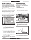
5. Tilt the table until the blade and table top
are perpendicular, then tighten the trunnion
cap screws.
6. Loosen the scale pointer for the cut angle
scale (on the trunnion) and point it to zero.
7. Loosen the feed angle cap screw and place
the machinist's square against the back of
the blade.
8. Position the table perpendicular to the blade.
9. Tighten the feed angle cap screws.
10. Loosen the pointer for the feed angle scale,
and point it to zero. The table and blade are
now calibrated.
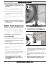
Guide Post Alignment
If the blade guide post does not raise and lower
exactly parallel with the blade, the clearances
between the blade guides and blade will change
as the guide post is moved, causing rubbing,
wear, and blade deflection. Blade guide clearance
must stay the same when the guide post is raised
and lowered along its full length of travel.
To align the guide post:
1. DISCONNECT BANDSAW FROM POWER!
2. Make sure the blade tracking and tension
are set correctly.
3. Lower the blade guide post to the bottom of
its travel and lock it in place.
4. Adjust the blade guides as described on
Page 26.
5. Unlock the post just enough to allow it to
slide, move it all the way up, then examine
the clearances between the blade and blade
guides to see if they changed.
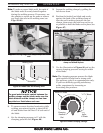
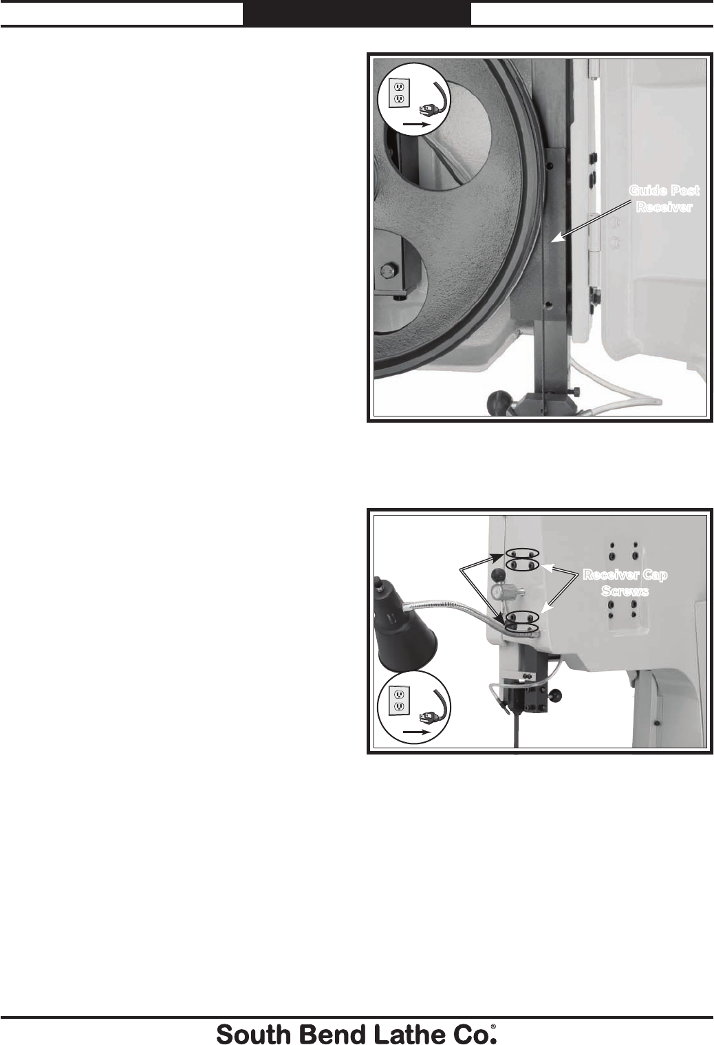
If these clearances changed beyond your
acceptable tolerances, the blade guide
receiver (Figure 42) can be adjusted to fix
this condition.
6. Using a 6mm hex wrench, loosen the four
guide post receiver cap screws (Figure 43).
7. Using a 5mm hex wrench, adjust the four set
screws to tilt the blade guide receiver in the
required direction.
8. Tighten the cap screws and recheck blade
guide clearance along the guide post path of
travel.
9. Repeat this procedure if necessary to fine-
tune the guide post travel to acceptable
tolerances.
Figure 42. Guide post system.
Guide Post
Receiver
!
Figure 43. Guide post alignment controls.
Receiver Cap
Screws
Set Screws
!