


10 ► IW24 User Manual
OPERATION
WRENCH TORQUE INFORMATION
FACTORS THAT AFFECT TORQUE
An impact wrench is a rotary hammer that impacts the
head of a bolt or nut. It does not apply a slow steady
torque as a standard torque wrench. Therefore, sever-
al factors affect the result of torque when using impact
wrenches:
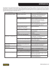
1. LONG BOLTS. Long bolts having high-friction
threads with lubrication under the bolt head or as-
sociated nut can twist when impacted, then untwist
before the next impact. This will especially happen if
there is low friction between the bolt head or nut and
the mating surface.
2. HEAVY, LOOSE OR MULTIPLE ADAPTORS.
Heavy, loose or multiple adapters between the
wrench and socket can dissipate the intensity of the
impact to the bolt head or nut.
3. AMOUNT OF IMPACT. Maximum torque results can
be obtained by allowing continuous impacting of the
socket against the bolt head or nut for at least 10
seconds.
4. HYDRAULIC FLOW RATE. If the ow rate to the
tool is too low, the hammer (or impact) speed is re-
duced. If the ow is correct, a change in the relief
pressure does not affect the impact force. Poorly
designed hydraulic circuits can result in lower ow
rates and reduced impact speeds when pressure is
required during impacting.
BOLT GRADE AND THREAD
RECOMMENDATIONS
Allowable bolt torque is limited by both bolt thread di-
ameter and grade of steel in the bolt. The IW24 Impact
Wrench is recommended for use on the following bolt
grade and thread sizes:
SAE Grade 2 1-1/2 inch to 2-1/4 inch/35-58 mm
SAE Grade 5 1-1/8 inch to 1-3/4 inch/28-44 mm
SAE Grade 8 7/8 inch to 1-1/2 inch/22-38 mm
PREOPERATION PROCEDURES
CHECK POWER SOURCE
1. Using a calibrated ow meter and pressure gauge,
check that the hydraulic power source develops a
ow of 7-12 gpm/26-45 lpm at 1800-2000 psi/124-
140 bar.
2. Make certain that the hydraulic power source is
equipped with a relief valve set to open at 2100-
2250 psi/145-155 bar.
3. Check that the hydraulic circuit matches the tool for
open-center (OC) operation.
4. UNDERWATER MODELS ONLY. Make certain
that the wrench impact mechanism is cleaned and
greased with waterproof grease after each day’s
use.
CONNECT HOSES
1. Wipe all hose couplers with a clean, lint-free cloth
before making connections.
2. Connect hoses from the hydraulic power source to
the tool ttings or quick disconnects. It is good prac-
tice to connect the return hose rst and disconnect it
last to minimize or eliminate trapped pressure within
the wrench.
3. Observe the ow indicators stamped on the main
body assembly and the hose couplers to ensure
that the ow is in the proper directions. The female
couple on the tools “IN” port is the inlet (pressure)
coupler.
NOTE:
If the uncoupled hoses are left in the sun, pressure
increase within the hoses can make them difcult to
connect. Whenever possible, connect the free ends
of hoses together.
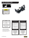
WRENCH OPERATION
The IW24 is designed for 1-1/2 inch square drive. The
1-1/2 inch drive conguration is used with drive sockets
for high impact (800-3500 ft lb / 1088-4760 Nm) nut and
bolt driving and screw anchor applications.
During normal operation it is common to see some
grease leakage from around the anvil during hard use.
Refer to the Service section in this manual for the cor-
rect lubrication procedures.
Use at the low end of the 800-3500 ft lb / 1088-4760
Nm torque range during continuous use over long peri-
ods of time (impact times exceeding 10 seconds). The
high temperature generated in the impact mechanism
can reduce steel part and lubricant durability within the
wrench.
1. Observe all Safety Precautions.
2. Move the hydraulic circuit control valve to the “ON”
position to operate the wrench.