


12V (e.g. due to a high load on the batteries), the entire charging voltage (> 15.5V) on the alternator. It usually means that the
cycle will be repeated. alternator’s own regulator has failed.
Troubleshooting
Unit is not working at all (no LEDs)
LED 8 - HIGH ALT TEMP, STOP (yellow)
After you have started the engine, check the voltage at the main
This LED will come on when the alternator temperature as
alternator input of the unit. You should be able to measure at least
sensed by the unit, is above 90°C. The charge cycle will be
13V. If you do not measure any voltage at all, it is possible that
suspended until the alternator has cooled down to 75°C or below.
your alternator requires a voltage on the output to fire up. (See
A flashing yellow LED means that the alternator-to-battery
Extended Installation.) In this case connect an extra wire from the
charger is overheated. The charge cycle will be suspended until
terminal named “STARTER SOLENOID” to the positive terminal
the unit has cooled down. If this fault occurs regularly, then the
of the starter solenoid.
unit must moved to a cooler location to protect it from permanent
If the input voltage on the unit is 13V or above and you still can’t
damage.
see any LEDs lighting up, check the internal fuse of the unit
and replace if necessary. If the new fuse blows again, please
LED 9 - UNIT FAILURE RHS (red)
contact the Sterling customer service.
This LED warns you that the unit’s integrated split charge diode
has failed on the right hand side. Restart the unit. If the fault
Unit is not boosting the voltage
persists, please contact the Sterling customer service.
Most regulators come set with a standard output between about
13.8V and 14.4V. If the standard regulator does not work within
LED 10 - UNIT FAILURE LHS (red)
these limits and has an output voltage below 13.8V, then the unit
This LED warns you that the unit’s integrated split charge diode
may not boost. In this case set the regulation voltage switch
has failed on the left hand side. Restart the unit. If the fault
to the “ON” position. This will drop the engine battery charge from
persists, please contact the Sterling customer service.
appr. 13V to appr. 12.8V which in turn improves the boost effect
on the domestic battery side.
Appendix 1: LED Information and Alarms
LED 1 - CONSTANT CURRENT (green)
A constant green LED (with LED 2 off) indicates that the unit is in
the bulk charge phase.
A flashing green LED indicates that the unit is in pause mode to
provide additional charge capacity for the starter battery.
LED 2 - TIME CONTROL ON (yellow)
This LED indicates that the voltage is approaching or has
reached the absorption level. It will come on only in addition to
LED 1.
LED 3 - FLOAT/POWERPACK (green)
This LED indicates that the absorption charge has been finished
and that the batteries have been fully charged. It remains on until
the unit is switched off or until the next charge cycle starts.
LED 4 - LOW BATTERY V (orange)
This LED will come on when the domestic battery voltage as
sensed by the unit, is below 13V. Often this indicates a defective
alternator or battery.
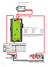
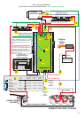
Appendix 2: Unit Connectors
LED 5 - HIGH BAT V/ TEMP (FL) (red)
A constant red LED means that the unit has tripped because of
TO DOMESTIC BATTERY BANK
high voltage at the domestic battery. Often, this indicates a failure
of the alternator regulator or another charging unit.
The positive connection leading to the domestic battery bank.
A flashing red LED means that the domestic battery temperature,
MAIN ALTERNATOR INPUT
as sensed by the unit, is above 50°C and that the charge cycle
has been suspended. Often, this indicates a defective battery.
The positive connection to be connected to the alternator B+
terminal.
LED 6 - BATTERY TYPE (yellow, green, red)
This LED displays the battery type that the unit has been set up
TO ENGINE STARTER BATTERY
for. It will be
The positive connection leading to the starter battery.
! yellow, for open lead-acid batteries,
NEGATIVE CABLE
! green, for gel batteries (Exide specification)
Connect this wire to the alternator negative. Extend as required
! flashing green, then off, for gel batteries (U.S. specification),
using a 60A cable.
and
! red, for sealed lead-acid and AGM batteries.
STARTER SOLENOID (optional)
The connection leading to the starter solenoid feed. (See
LED 7 - HIGH ALT VOLTS (red)
Extended Installation.) Use only if required!
This LED indicates that the unit has tripped because of high
(7)
(14)
(17)
(4)
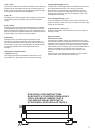
Check the voltage and, if
necessary, stop your engine as soon as possible and disconnect
the alternator input cable, or you will boil and destroy your
batteries!
Warning: Do not do this unless you have the above-described
problem as this could result in a low engine start battery
performance.
Make sure alle cables used have a suitable size!
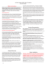
CONSTANT CURRENT
Slow flash = inactive
TIME CONTROL ON
FLOAT/POWERPACK
LOW BATTERY V
HIGH BAT V/ TEMP (FL)
BATTERY TYPE
HIGH ALT VOLTS
HIGH ALT TEMP STOP
UNIT FAILURE
UNIT FAILURE
1
2
3
4
5
6
7
8
9
10
REMOTE DOM SENSE (optional) REMOTE CONTROL (optional)
The connection leading to the positive terminal of the domestic Connection for the optional remote control.
battery. (See Extended Installation.) Installation is optional.
ALTERNATOR INPUT SHUNT (optional)
ALTERNATOR TEMP SENSOR (optional)
Connection for the alternator input shunt which is part of the
Connection for the alternator temperature sensor. Installation is remote control package.
optional.
STARTER BATTERY SHUNT (optional)
BATTERY TEMP SENSOR (optional)
Connection for the starter battery shunt which is part of the
Connection for the battery temperature sensor. Installation is remote control package.
optional.
(3) (5)
(2)
(1)
4 5
1
16
31
46
61
76
91
106
121
136
151
166
181
196
211
226
241
256
271
286
301
316
331
346
361
376
391
406
421
436
451
466
481
496
511
526
541
556
571
586
Time min.
Amps
100
90
80
70
60
50
40
30
20
10
0
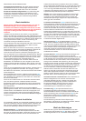
amps
domestic battery current
starter battery bank current
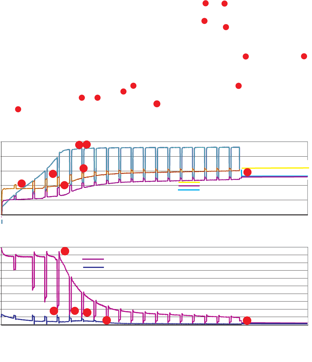
Domestic battery bank current curve, with engine battery bank current curve
9
time in mins
8
7
10
11
12.50
13.00
13.50
14.00
14.50
15.00
9
18
28
37
46
55
64
73
83
92
101
110
119
128
138
147
156
165
174
183
193
202
211
220
229
238
248
257
266
275
284
293
303
312
321
330
339
348
358
367
376
385
394
403
413
422
431
440
449
458
468
477
486
495
504
513
523
532
541
550
559
568
578
587
596
TIME min.
Volts
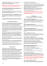
alternator input voltage
starter battery voltage
domestic battery voltage
time in mins
volts
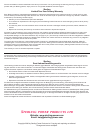
Engine battery bank, domestic battery bank, and alternator voltage curves
4
5
2
3
1
6
10
What do I expect to see from this unit and why?
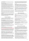
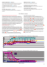
The current graph
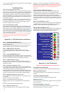
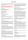
System Voltage Graph
This is what the process is all about.
The below test was set up and monitored and is as close as The steps on the graphs show the unit boosting every 15
possible as to what happens on the average split charge system. minutes, then resting for 2.5 minutes. An example of this is the
The engine battery is a 100 amp hr standard lead-acid, and the time period between and . What you can see here is that by
domestic battery is 3 x 100 amp hr standard lead-acid. The engine switching off the amplifier (to help the engine battery getting more
battery was discharged to 11 volts (about 10 engine starts) and charge), the engine battery voltage curve increases during that
the domestic bank to about 11 volts (will no longer run an inverter step shown at point which results in extra current going into
and is about 60% empty). The alternator used is a Bosch 90 amp the engine battery at position . The current change of this
with a standard 13.9 volt (variable) regulator. The unit battery type process is reflected in the other graph marked ‘the current graph’.
is programmed to open lead-acid. There are two graphs, one is shows the current flow into the engine start
showing the current going into the batteries, and the other is battery and the domestic system. The effect of the amplifier can
showing the various voltages on the system. be clearly seen when the unit switches off for its 2.5 minutes rest
: cycle. The current drops from position = 95 amps to position
The key points to pick up on here are: = about 20 amps, a huge difference. At the same time you can
The yellow trace (alternator voltage into the unit) clearly shows see the extra current going into the starter battery which clearly
that the system is doing its job. It is designed to pull this voltage charges through the whole exercise.
down a little in order to enable the standard alternator regulator to On completion the unit switches off, and the process continues as
produce its full current. You can clearly see that on position on a conventional split charge system . If however the domestic
the voltage curve the voltage is pulled down to position . The battery falls below 12 volts, the system will automatically restart
current has increased from position - which is about 70 and continue the process again.
amps improvement. shows that the engine battery has been fully charged and is
Position : This is the magic point, the point where the taking no more current.
domestic battery voltage exceeds the alternator input voltage.
2
1
4
6
7
3
5
8 9
10
11
UNIT EXPECTATIONS
9
12
12